Intro
Lets use a Blueprint Actor with extended Construction Script logic in order to improve our work practices.
We have went through all four previous entries of this tutorial series. We have created the geometry, textures and then shaders necessary for getting the nice visual end result. We could leave it there. The VFX vision is accomplished.
However, there is one final, optional step I wanted to run you through. It’s the set up of a custom Blueprint Actor and a few lines of Construction Script node logic.
If you would like to remind yourself of the previous tutorial steps, you can do so over here:
Part One - Creating Static Geometry
Part Three - Making Polar Coordinates Shader
Part Four - Adding Refraction Shader and Assembling The Final VFX
Tip:
As in all parts of this tutorial series, I am working in UE5.3. If you are inside UE4, you can still follow along and should not have any issues replicating any part.
If you are happy with what you have, you can skip this final part. If you want to learn more about Blueprints and Unreal, stick around.
Here is a reminded of what we have accomplished so far:
Videos Preview
(Youtube embedded video above, showcasing the final vortex VFX we will be creating.)
(Youtube embedded video above. Shows the VFX basin duplicated three times. One is blue, the other is purple, the last one is green.)
The Problem
I like the visual result and the set up of our work so far. The VFX vortex basin looks cool. It looks how we wanted it. I have a “problem” with a part of its set up that has nothing to do with the visuals though. I say “problem” because its not a large issue per se.
It’s more about efficiency than about any “problem”. There is an overall lack of efficiency that shows up in a few ways. Lets look over it.
Not Bundled
For a started, our VFX basin is composed of four pieces:
- Static vortex mesh with base color.
- Static vortex mesh copy with refraction.
- Middle small static mesh plane to fix imperfection.
- Cylinder static mesh frame.
As such whenever I want to copy my visual into a new level, or make a duplicate in the existing level, I have to select all one by one, as seen in the image below.
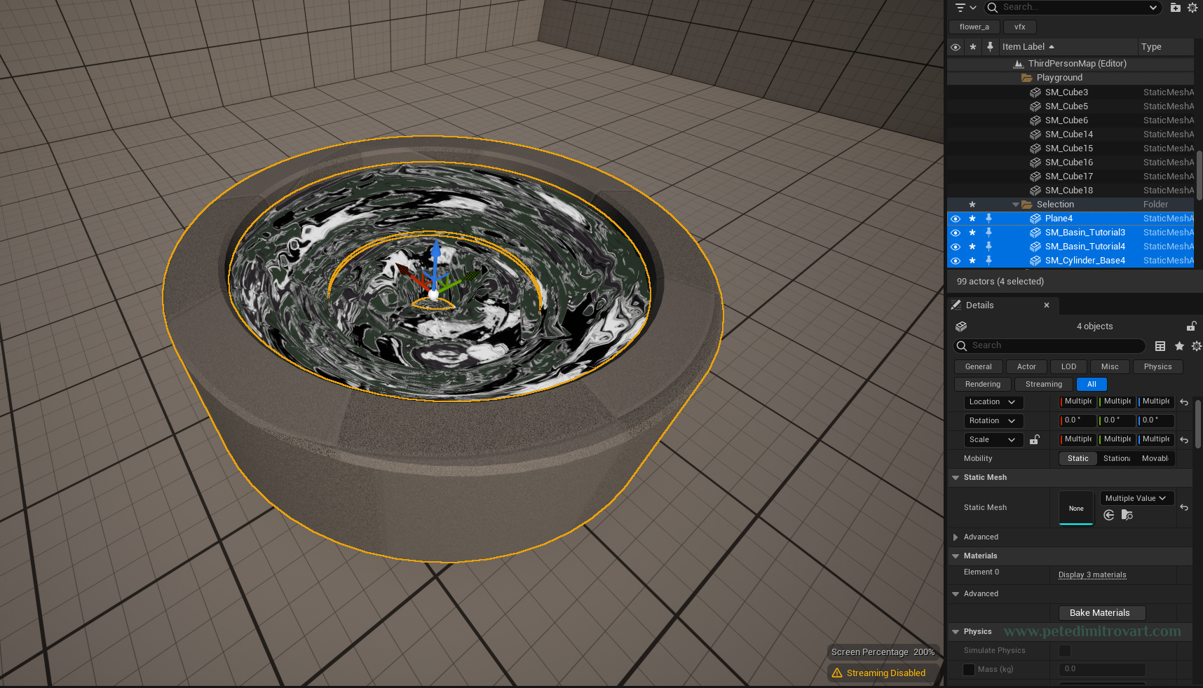
Lets imagine a hypothetical situation where this asset is used in a full production game, where lots of artist work on the game. First, selecting one by one four assets, whenever you want to move things around is inefficient. Second, having to “instruct” and have other artists remember about your edge case VFX where its split into four pieces is also quite inefficient.
There is a solution to that. It is to turn the four pieces into a bundle. Into a Blueprint Actor. We will do that and cover the necessary steps. Any artist, designer or a programmer that later on has to work with this VFX basin, add functionality or do tweaks, will be thankful to us for bundling it properly into an actor.
Hard to Change Color
If you remember from the previous steps, we made our main material shader so we can tint the VFX into any color we like. That is the reason why in part two of the tutorial series we left the “albedo” liquid-spill texture black and white - so we could tint it in engine.
As such, lets imagine another hypothetical situation with a game in full production. Let us say that this VFX basin is used as a portal or as some fundamental for gameplay function. As such it will exist everywhere. Lots of copies in each world. Also lets say that for visual variety, or even better, for design functionality, we have created a big array of lots of colored versions of this VFX basin. Its not going to be just blue, purple and green like the previews above.
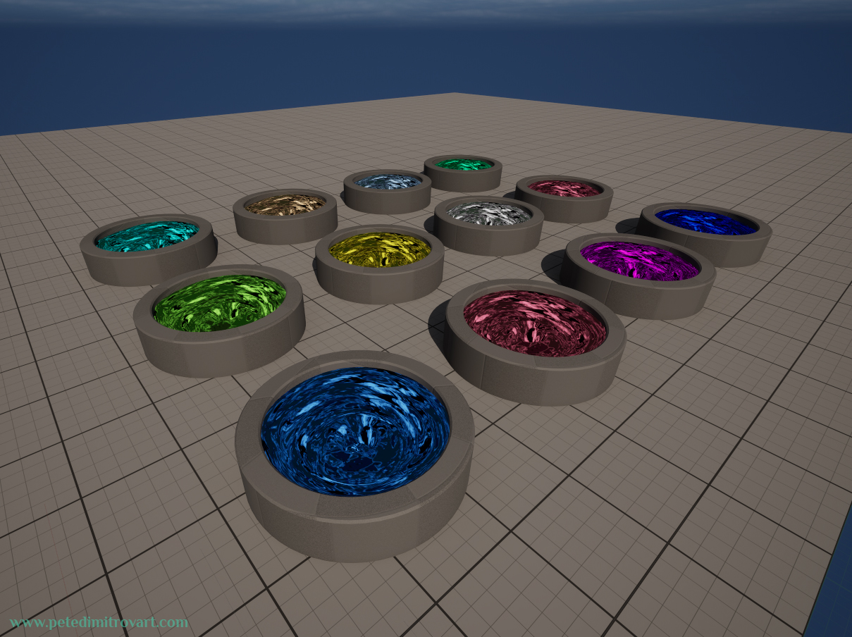
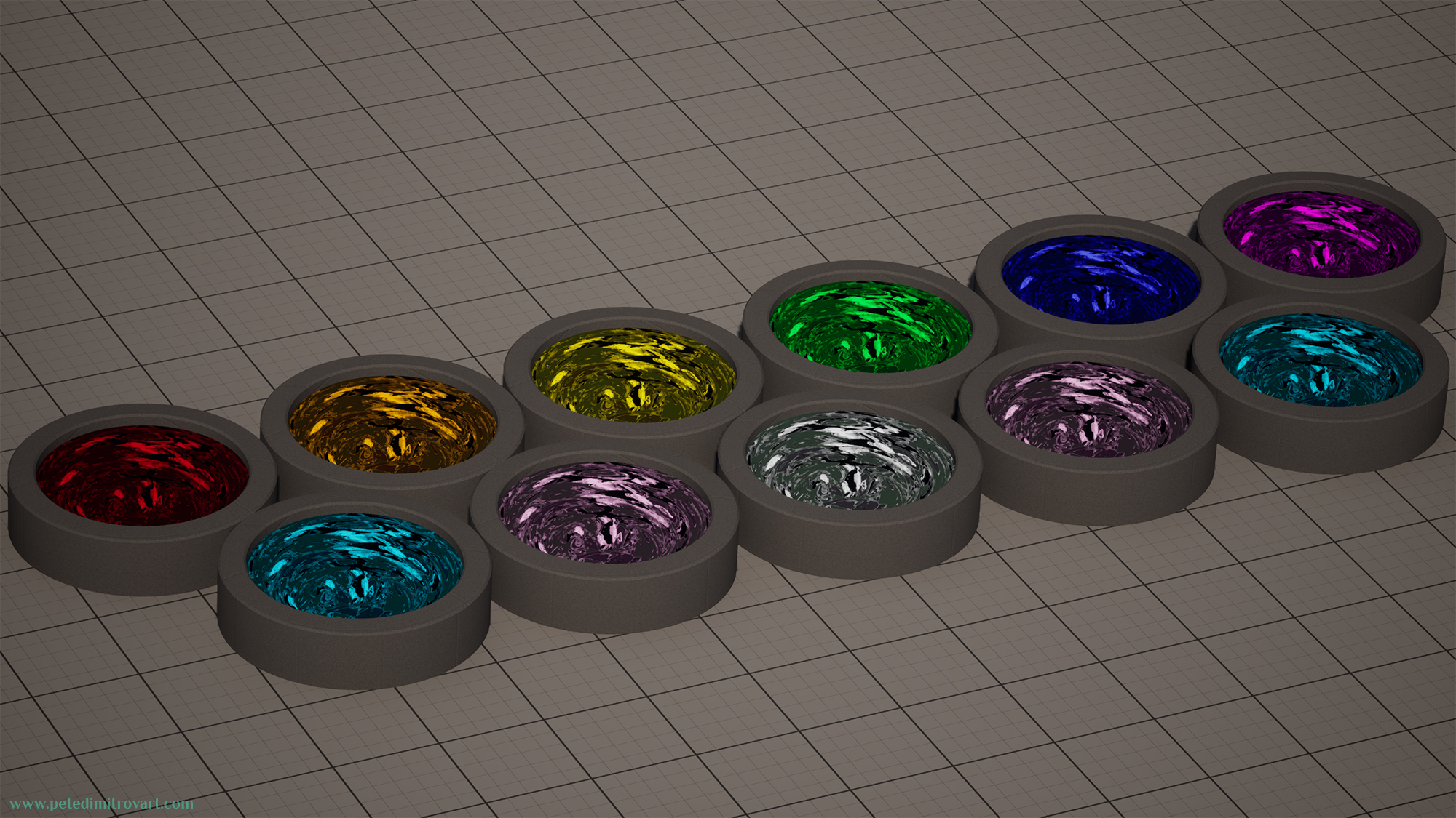
Instead its going to be blue, purple, green, violet, pink, red, yellow, cyan, a shade of black, a shade of white, and more. Also lets imagine that new artists or designers joining might want newer shades of colors, so they suddenly create even more. Our Content Browser ends up like this:
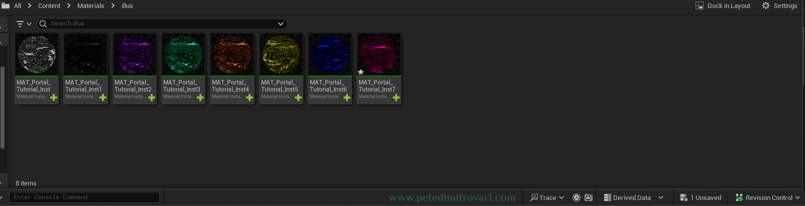
I had the patience to make only 9 material instances to illustrate this point. But imagine there being 18, or 25 or even 30 material instances. Believe me, I’ve seen productions at previous game dev jobs I’ve had where this thing happens. I didn’t name the instances properly either - instead of having a color in the name, they just go _Inst1…Inst2…InstN. and I’ve seen that in studios out there too (make sure to always name things properly).
The Solution
In order to make something more efficient and eliminate the two issues above, we can create a Blueprint Actor. In it, all static meshes will be into a collection, which fixes problem one. Then in the Construction Script of the blueprint, we can use few nodes of logic in order to make it so we have exposed and customizable color per blueprint actor instance once placed in the world.
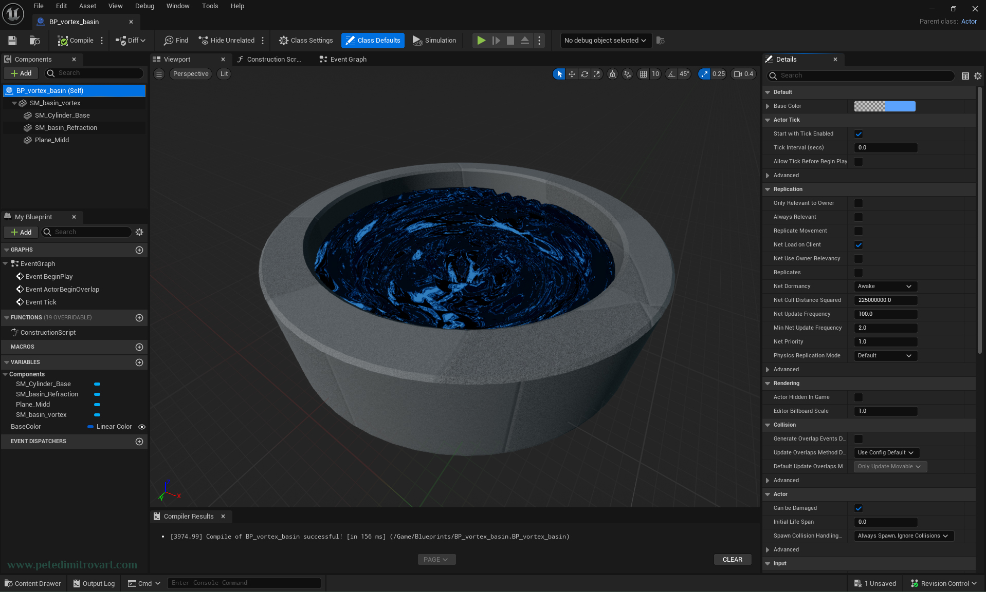
We will end up with this.
Blueprint Actor
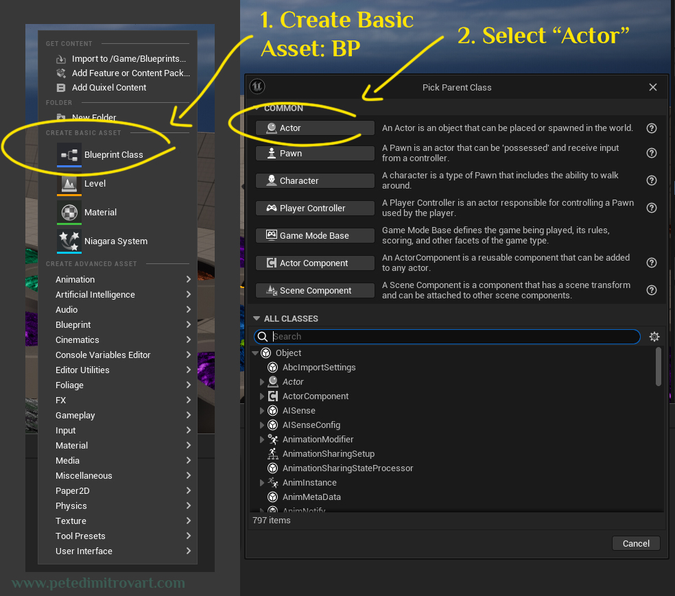
In your project directory, make a folder called “Blueprints”. Inside of it, right click to create a new asset. Under “Create Basic Asset”, select “Blueprint Class”. In the window that pops up, select the top option button, called “Actor”.
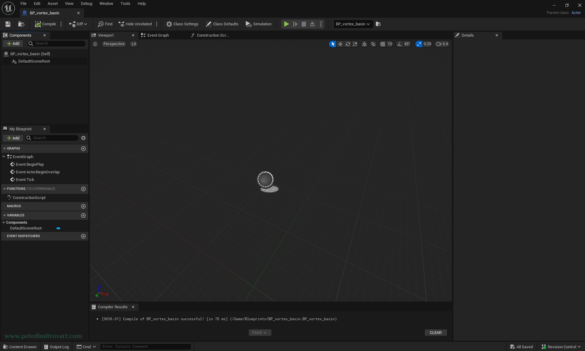
For a name of your Blueprint go for something easy to understand and follow like “BP_vortex_basin”. Open the newly created blueprint.
Adding Components
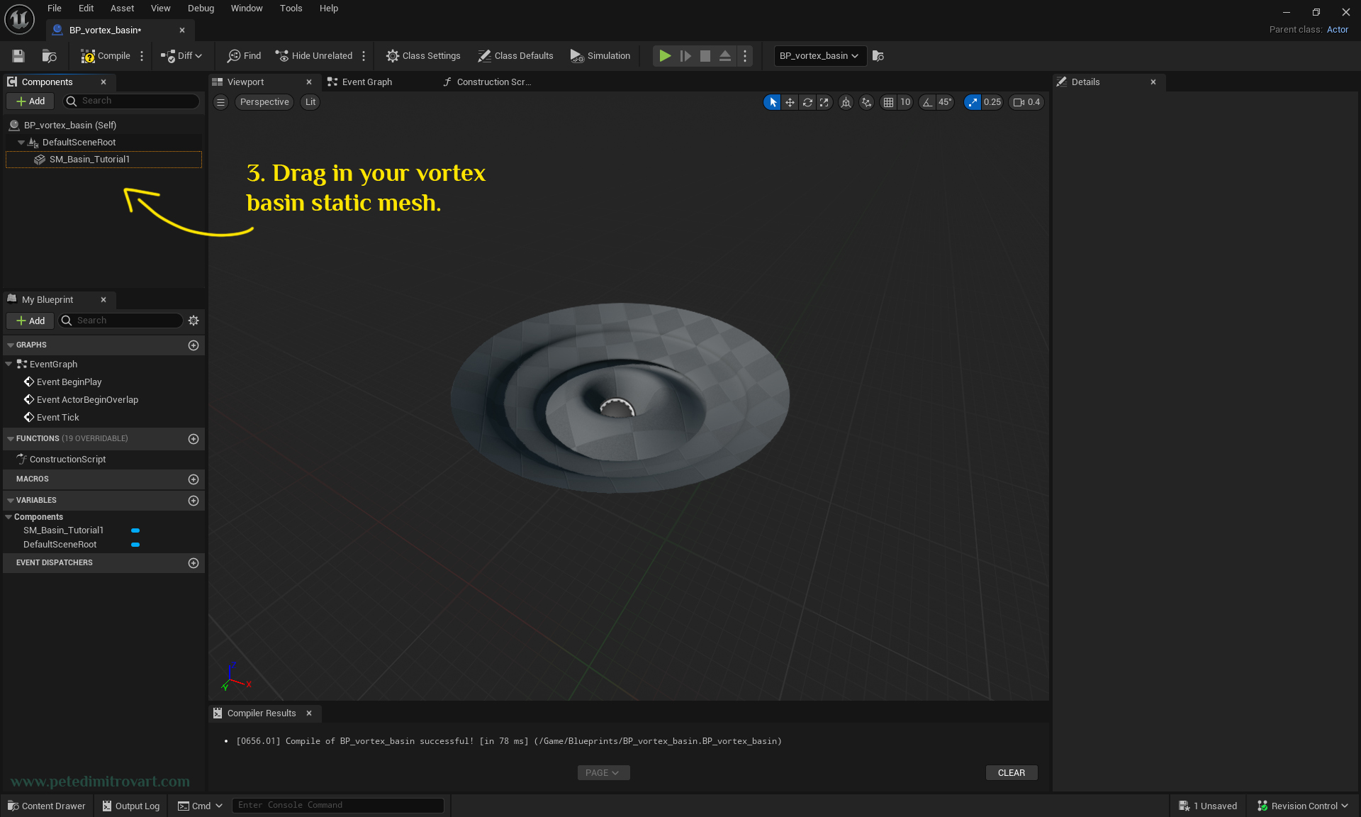
Find the static mesh you created in the first part of this tutorial series. From the “Content Drawer” drag it into the Blueprint.
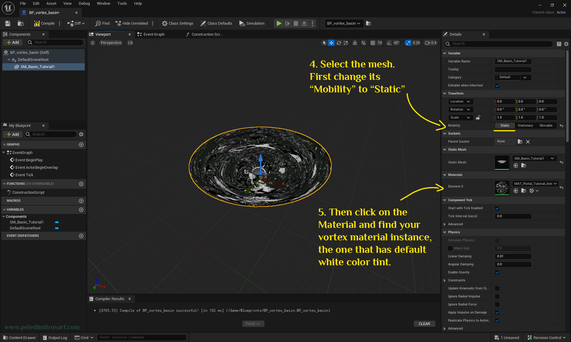
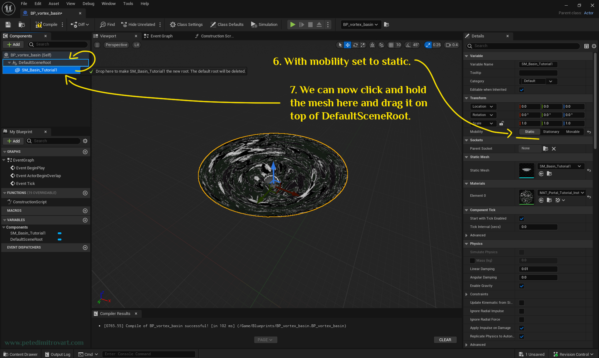
Select the newly added mesh. On the right hand side panel, first change the “Mobility” from “Movable” to “Static”. Then click on the Material and find your vortex material instance, the one that has default white color tint on it.
With mobility set to static from the previous step, we can now click and hold the mesh on the left hand side of the screen and then drag it on top of “DefaultSceneRoot”.
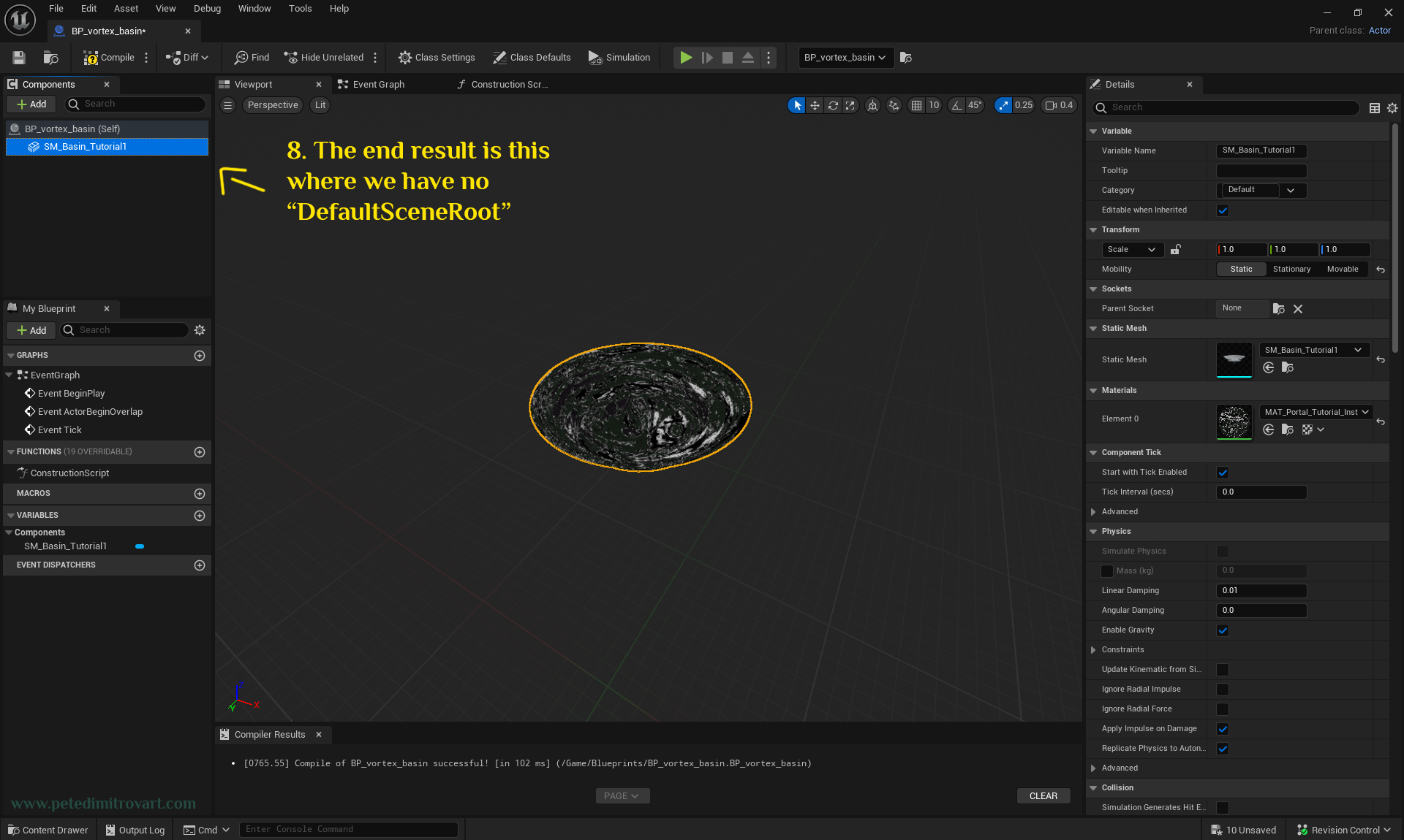
The end result is this where we have no “DefaultSceneRoot”.
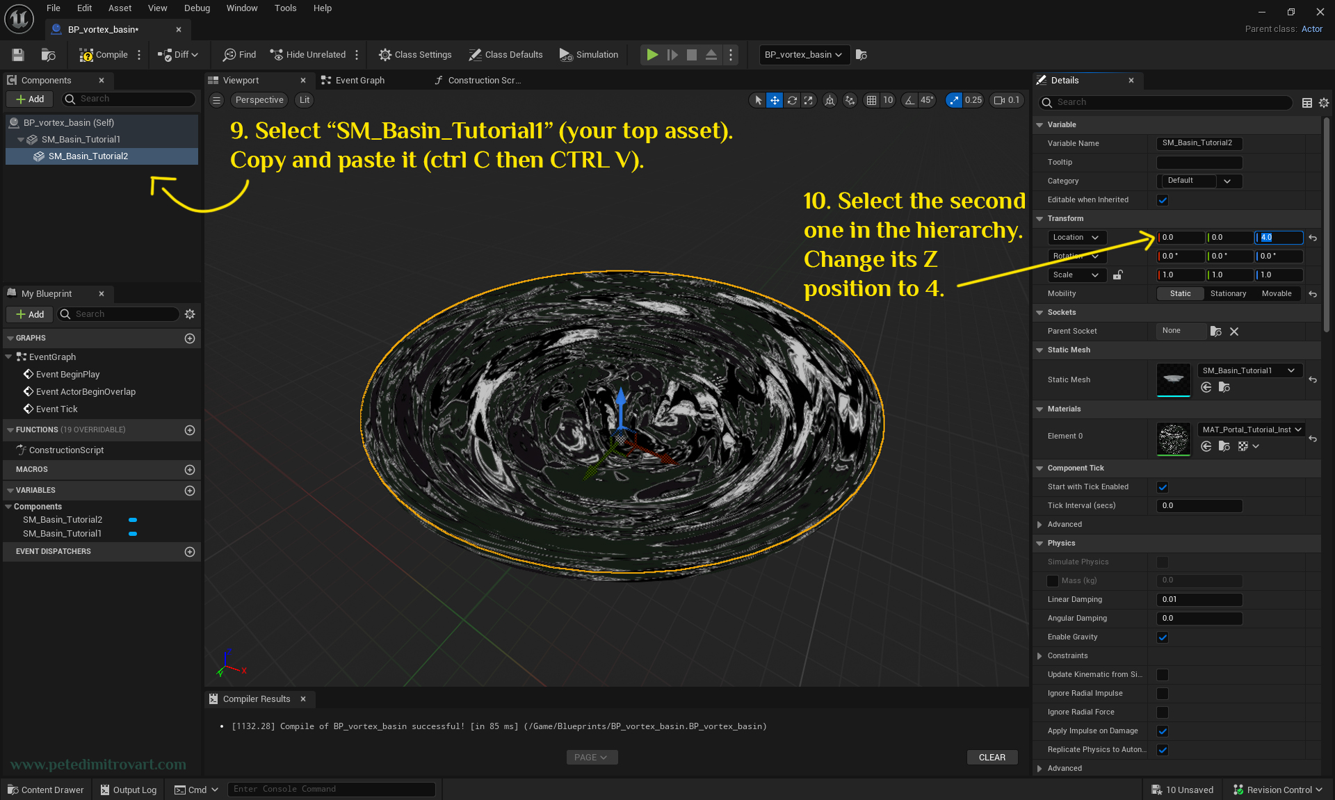
Select “SM_Basin_Tutorial1” (your top asset in the hierarchy to the left, the name might be different for you). Copy and paste it (do so by pressing CTRL + C and then CTRL + V immediately, while hovering the mouse over the hierarchy window oon the left). Select the second, new copy, in the hierarchy. Change its Z position to 4 by using the Details panel to the right.
Rename
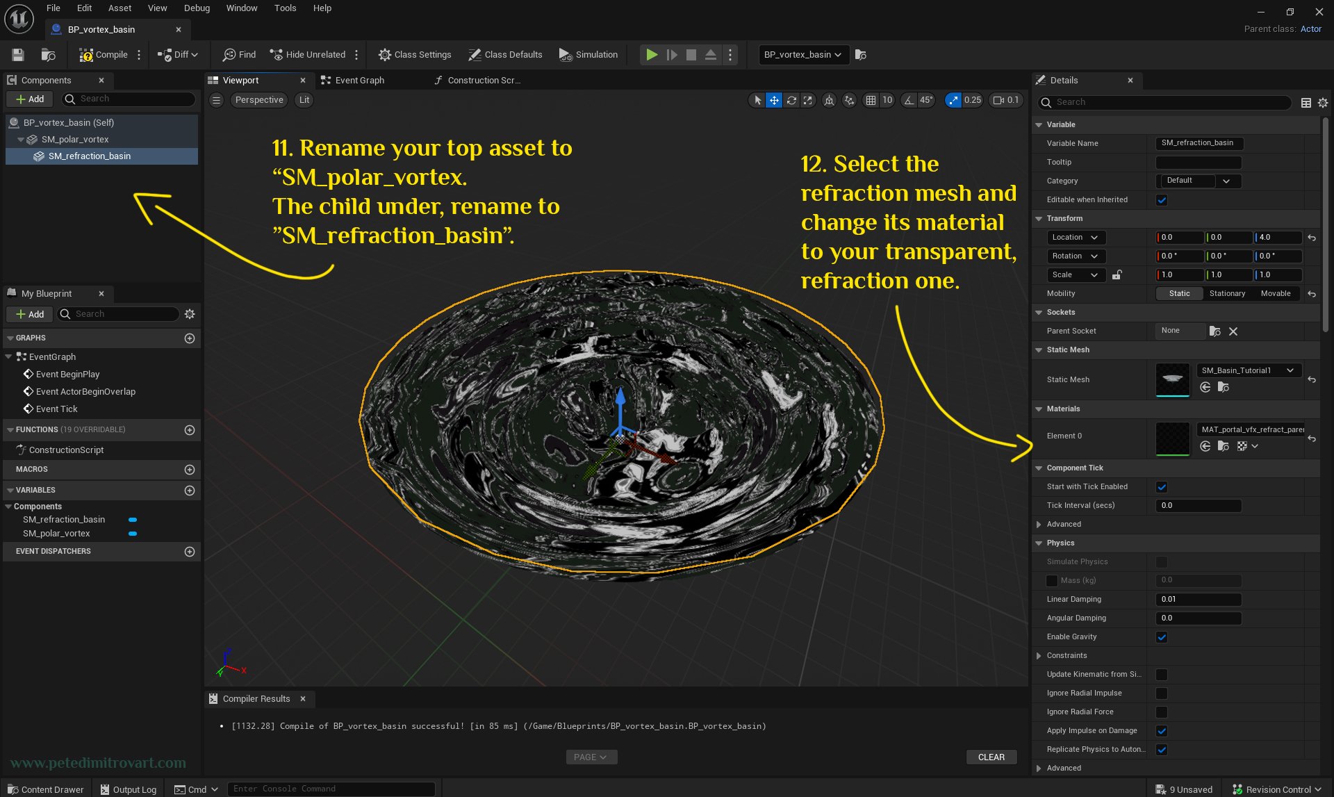
Rename your top asset to “SM_polar_vortex”. The child component (asset) under, rename to “SM_refraction_basin”. Select the refraction mesh and change its material to your transparent, refraction one from the previous part in this tutorial series.
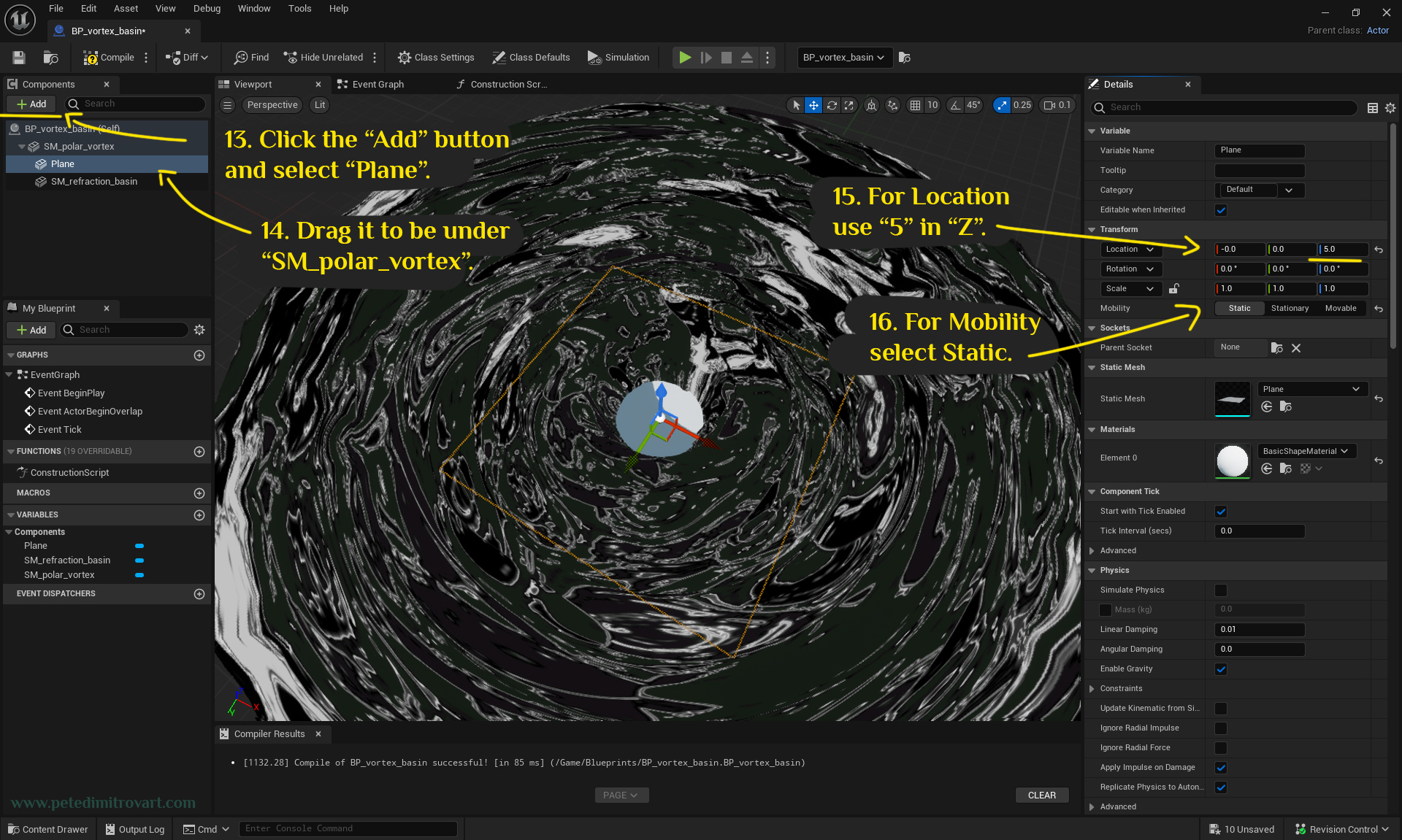
Click the “Add” button below the “Components” in the top left corner. Select “Plane” from the “Add” subcontext menu. Drag the plane to be under “SM_polar_vortex”. Change its Z location setting to “5”. For its “Mobility” change from “Movable” to “Static” as per usual.
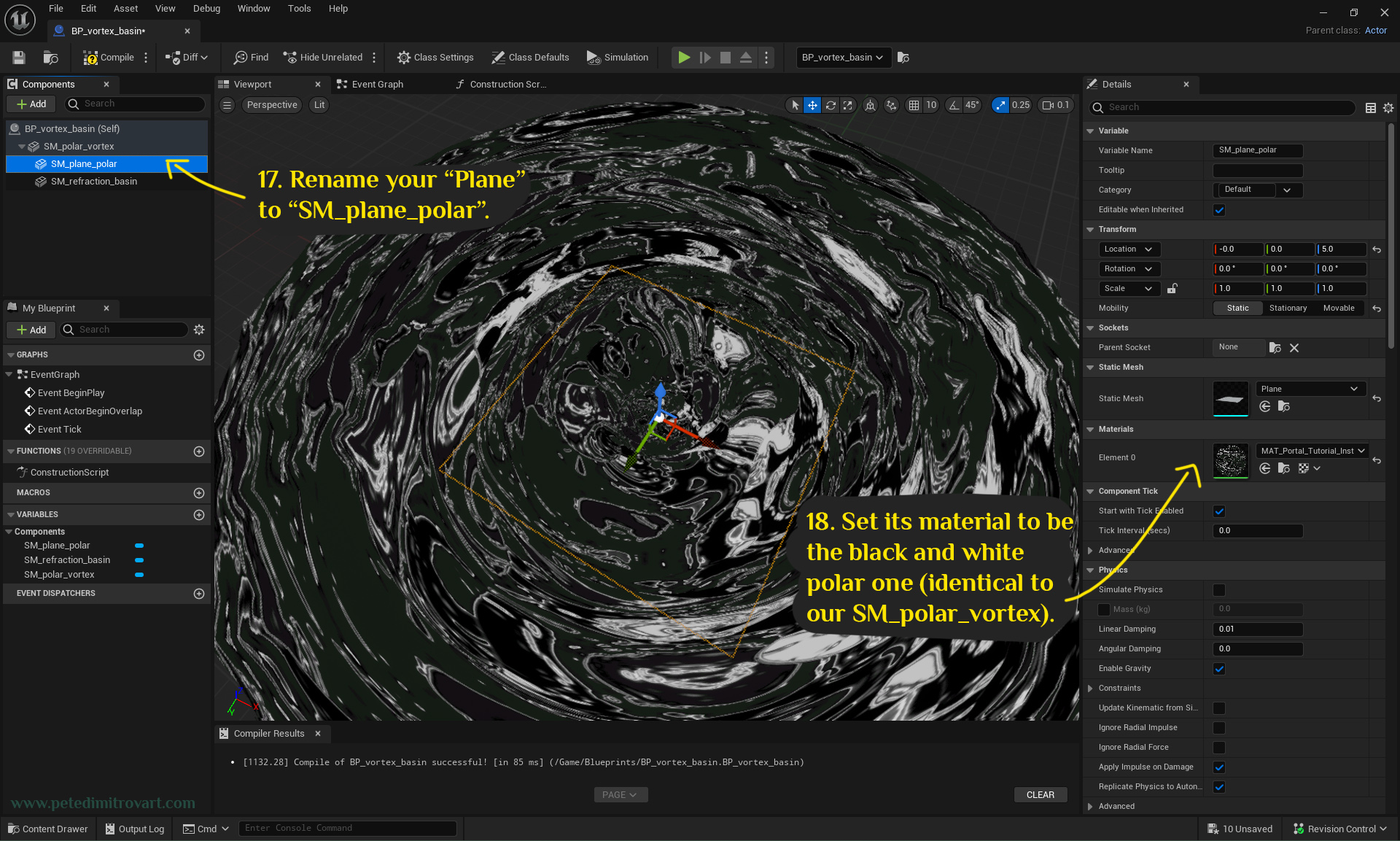
Rename your “Plane” to “SM_plane_polar”. Set its material to be the black and white polar one (identical to our SM_polar_vortex).
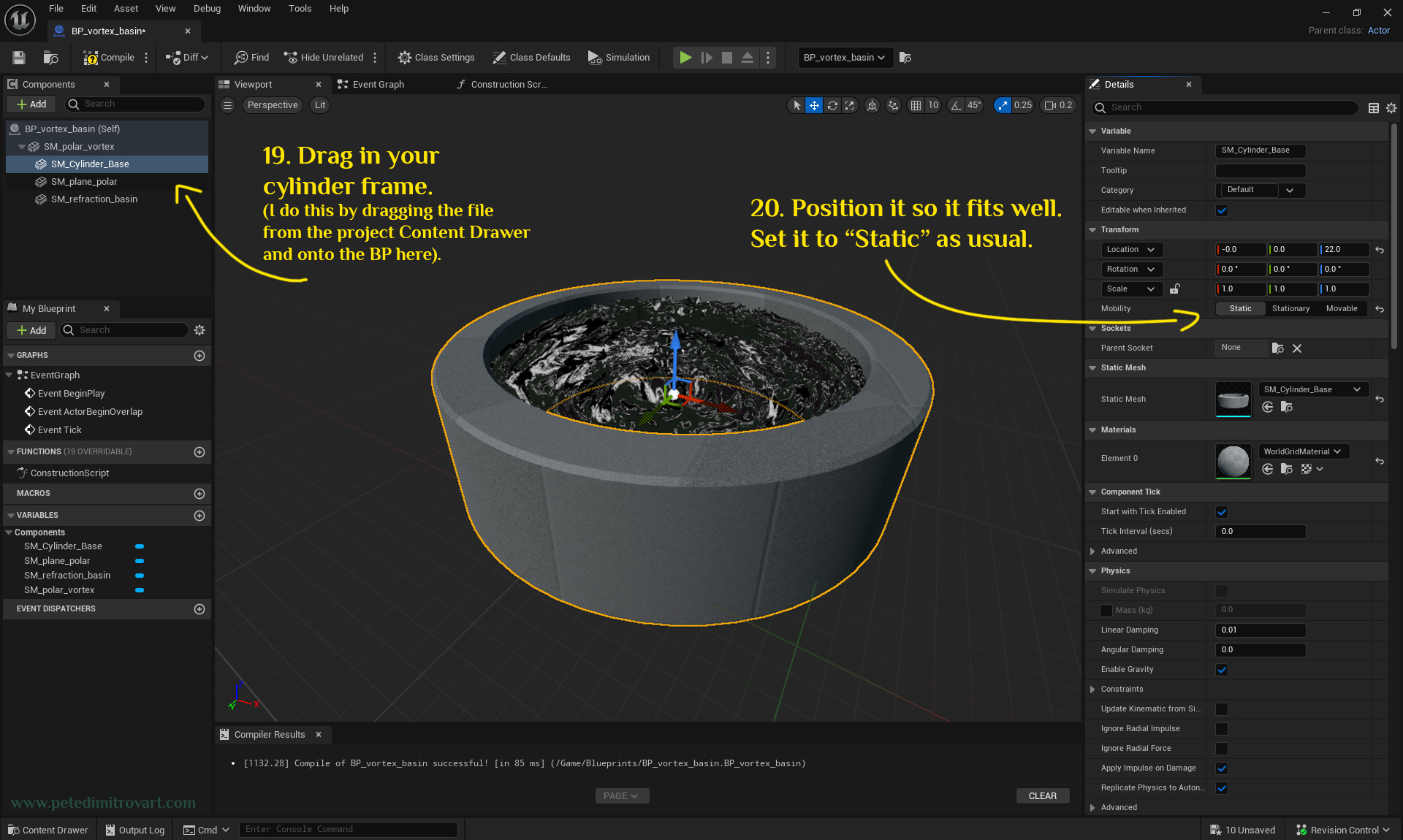
Drag in your cylinder frame mesh (I do this by dragging the file from the project Content Drawer and onto the BP here). Position it so it fits well. Set it to “Static” as usual.
Construction Script
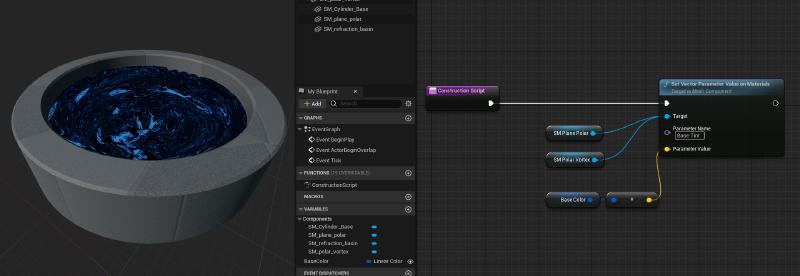
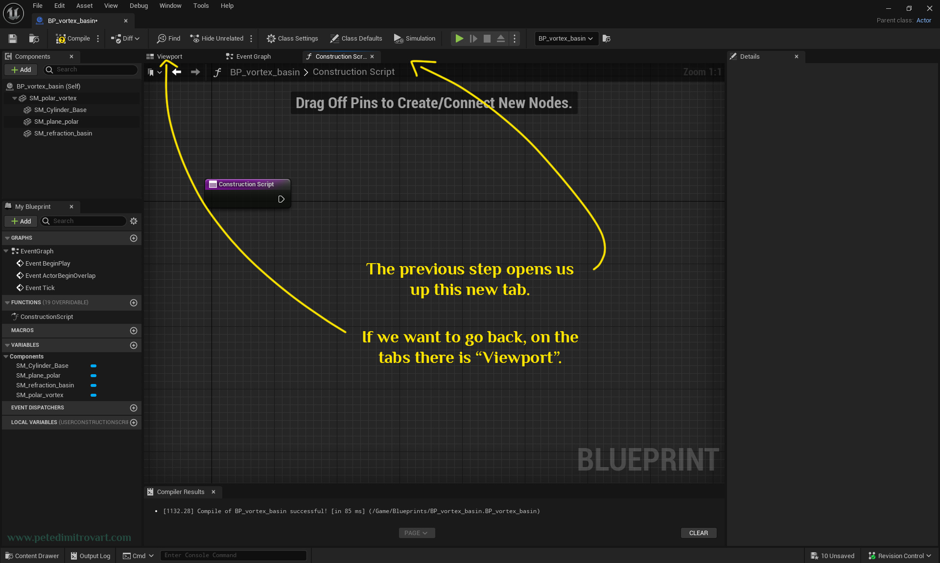
Double click on the “ConstructionScript” function that is listed in the image seen below (yellow arrow points at it).
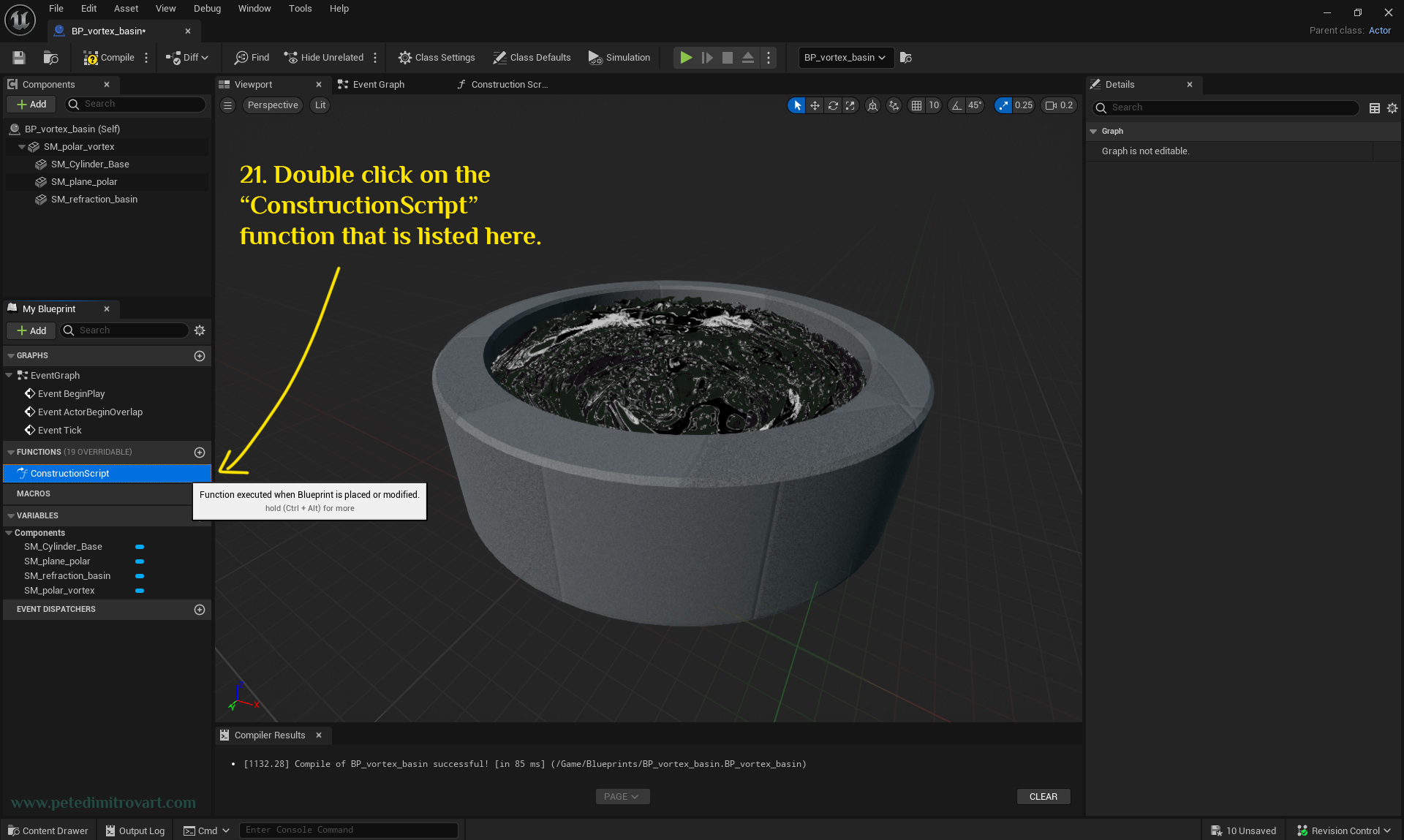
After double clicking on the “ConstructionScript” seen in the previous image, a new tab opens. If we want to go back on the top part of the screen, there is a tab called “Viewport” (we are not going back now, just saying).
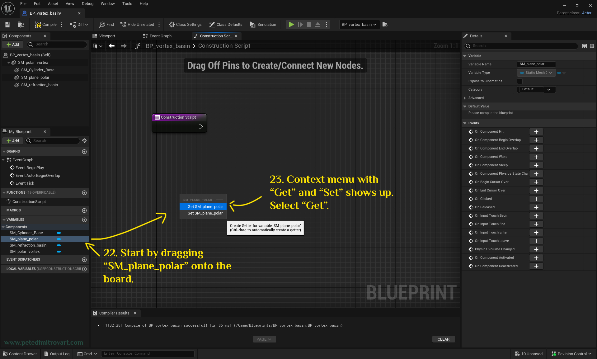
On the left side, there is a category called “Components”. Expand it. Inside you will see the collection of “SM_” pieces you have in the blueprint.
Start by dragging “SM_plane_polar” onto the board. Context menu with “Get” and “Set” shows up after you drag. Select “Get”.
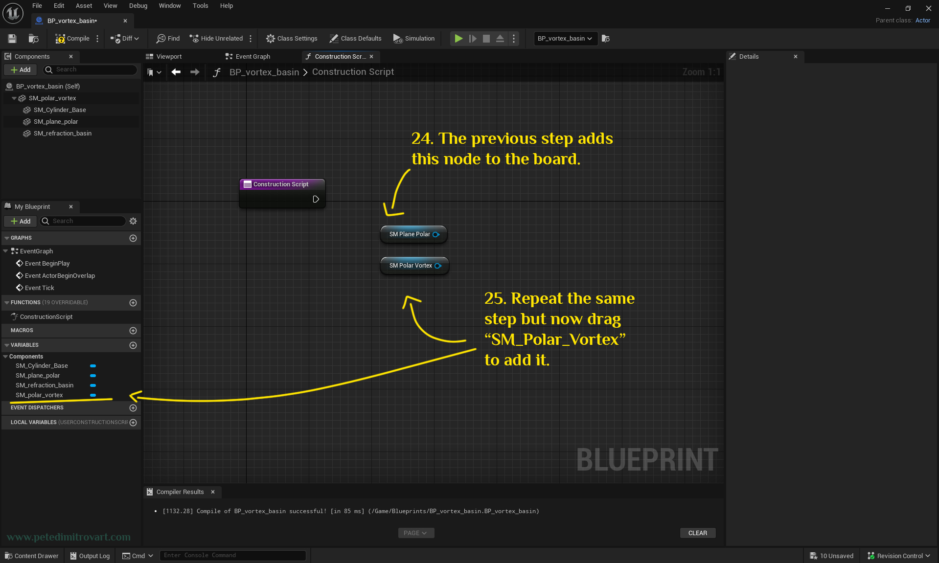
The previous step adds this node on the board, seen below - blue tinted “SM Plane Polar” named on. Repeat the same step but now drag “SM_Polar_Vortex” component from the left menu. Add it to the board.
Set Vector Parameter
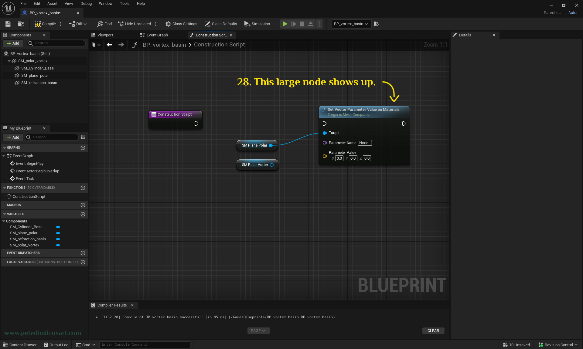
Start dragging the pin out of “SM Plane Polar” blue node. Let go and this search seen below will appear. Type in “set vector parameter” and select “Set Vector Parameter Value on Materials” that will appear in the list.
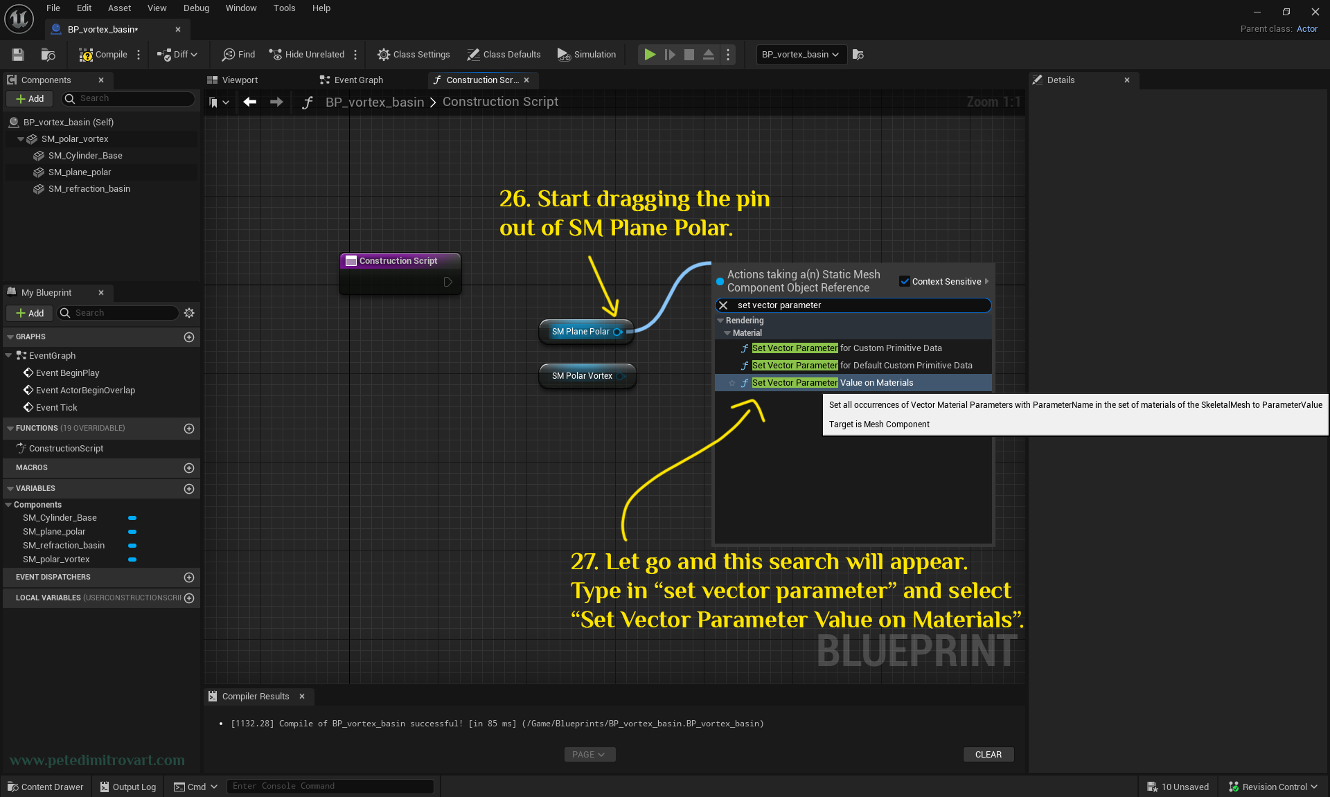
This large node shows up (seen below).
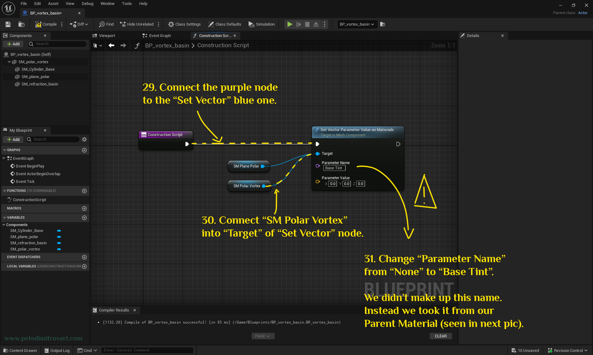
Connect the purple node to the “Set Vector” blue one (I’ve highlighted it in yellow, broken line below). Connect “SM Polar Vortex” into “Target” of “Sec Vector” node. Change “Parameter Name” on the “Set Vector” large node from “None” to “Base Tint”.
We didn’t make up this name. Instead we took it from our parent material.
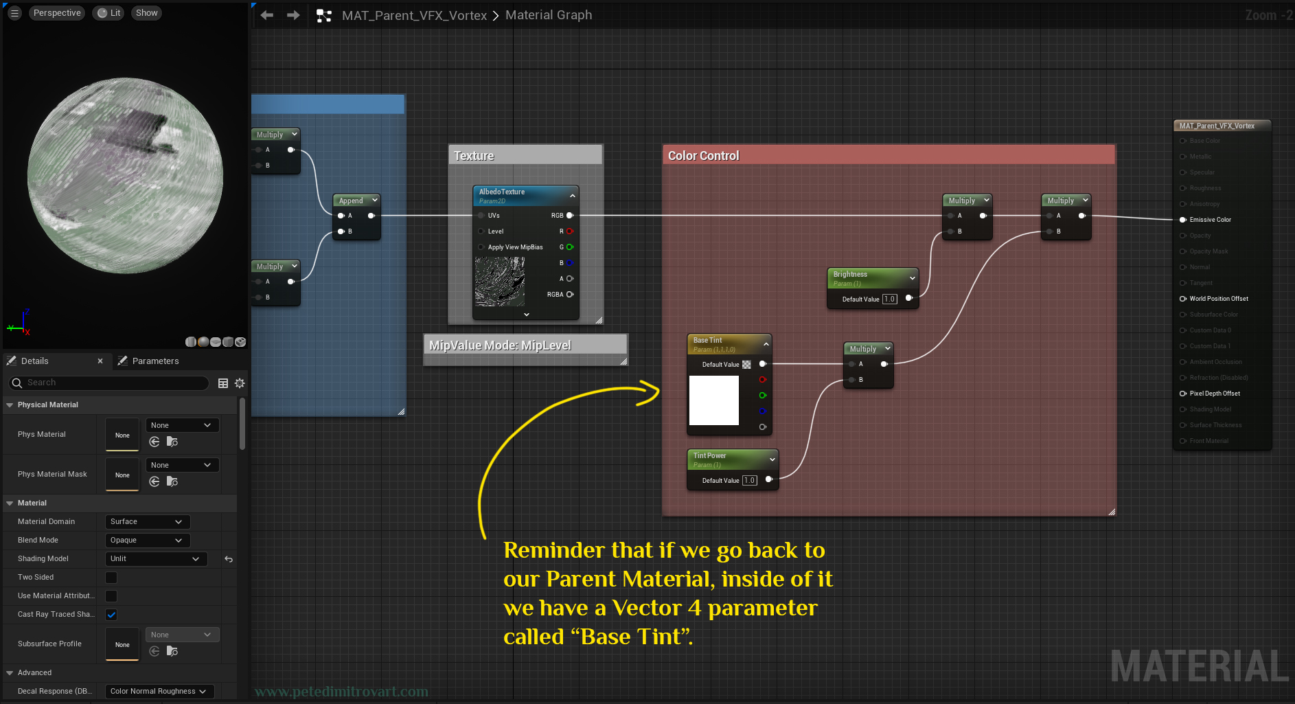
This image below is a reminder that if we go back to our parent material, inside of it we have a “Vector 4” parameter called “Base Tint”.
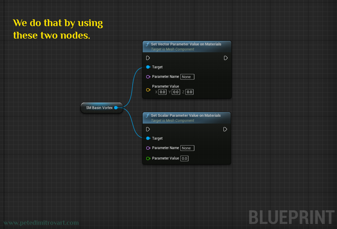
In our material instance that we edit through the construction script, we can also see our “Base Tint” parameter. In fact any of the “Scalar Parameters” or the “Vector Parameters” seen in here, we could edit, if we wanted to.
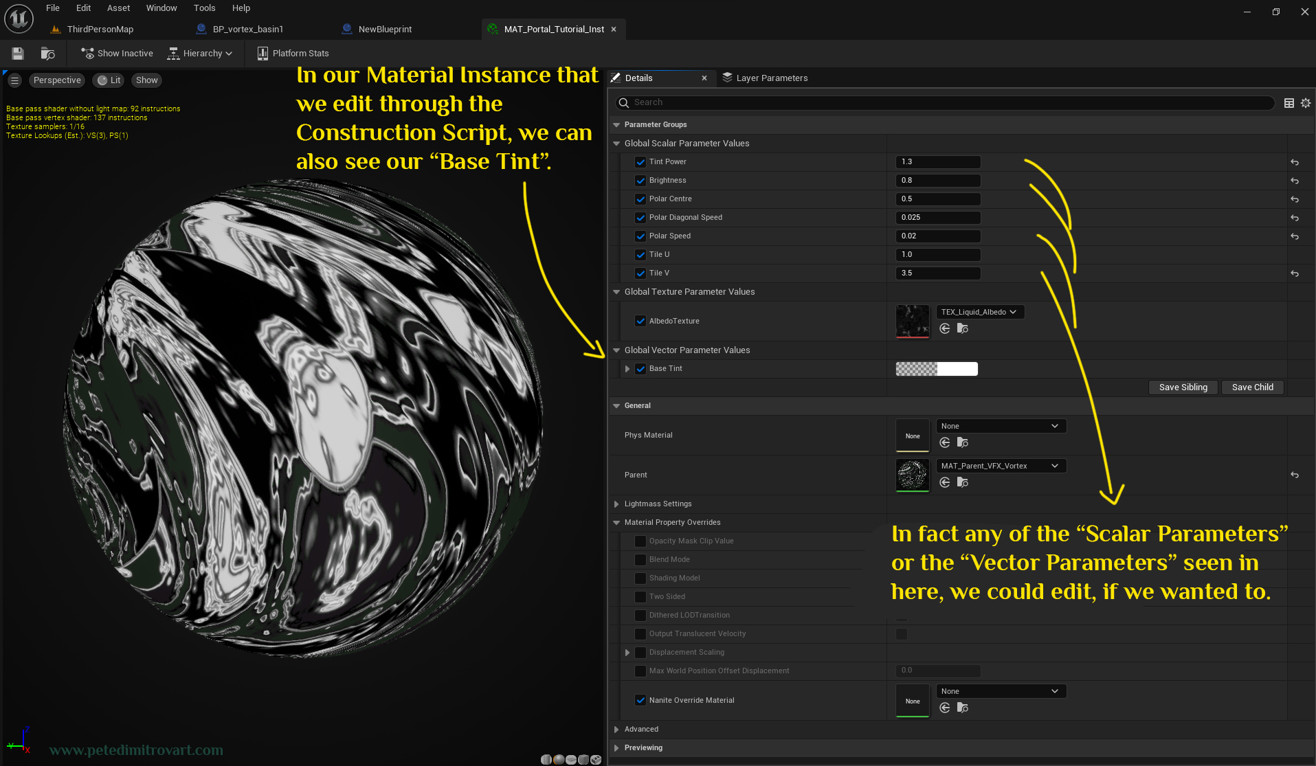
We do that by using these two nodes.
Note:
From all of the descriptions and material vs construction script images you see above, you hopefully learned that we need to be careful and track exactly how we name our parameters inside of the material graph. We then use the names inside of our new blueprints, as exactly seen over in the material. If in your material you named your Base Tint to something different, then don't copy that name from me, instead use the name you came up with back when you were making your material shader.
New Variable
With all pins connected and with the “Parameter Name” of the “Set Vector” node put correctly, now lets create a new Blueprint Variable.
Click on the (+) sign seen below to add a new variable.
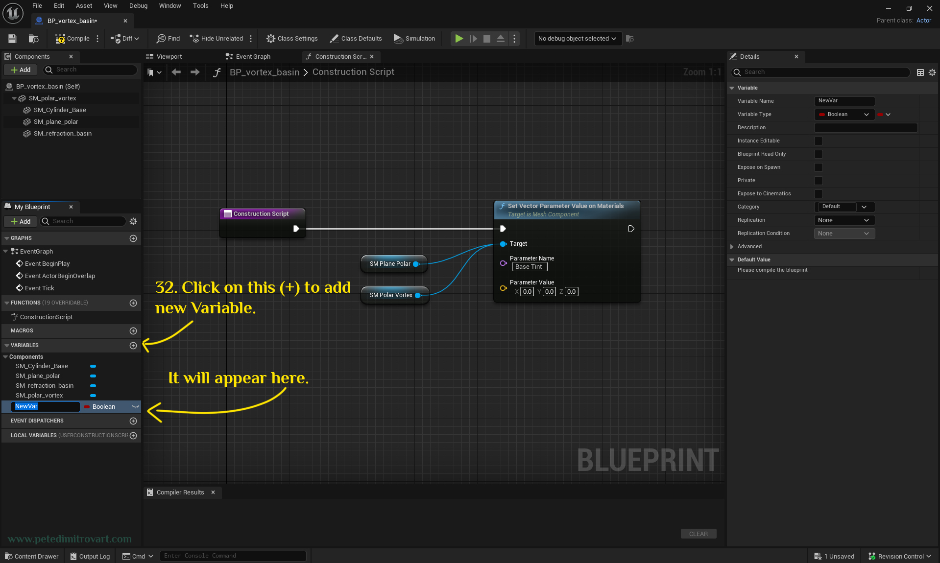
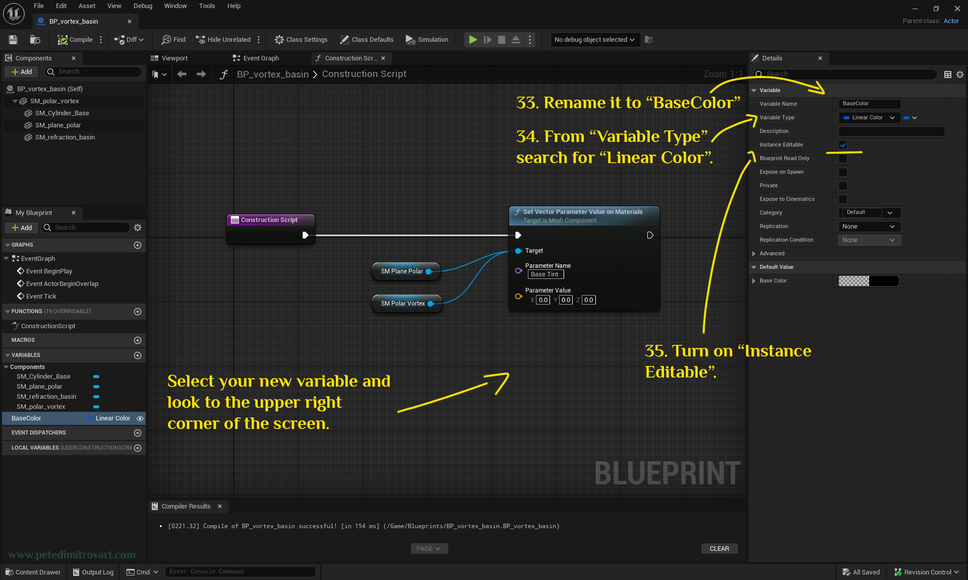
The newly created variable, name “BaseColor”. You can do so by selecting the “NewVar” red boolean and then changing its name on the panel in the right hand side. From “Variable Type” over in that corner, search for “Linear Color” and set it to that. The red boolean indicator will turn into a dark blue Linear Color indicator. From the settings over there also turn on “Instance Editable”.
Instance Editable turned on, in the settings there, is very important as that is what will let us change the color when we drag a blueprint instance in the open world.
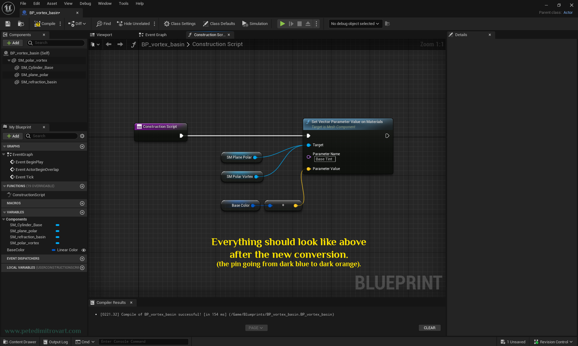
Drag “BaseColor” from the left side onto the board. From the context menu that shows and asks if you want to “Get” or “Set” the Base Color, pick “Get. The node seen below will show up. Connect Base Color node pin into “Parameter Value” of “Set Vector Parameter Value on Material” node seen below. It will do a conversion for us (seen in the picture after the next one).
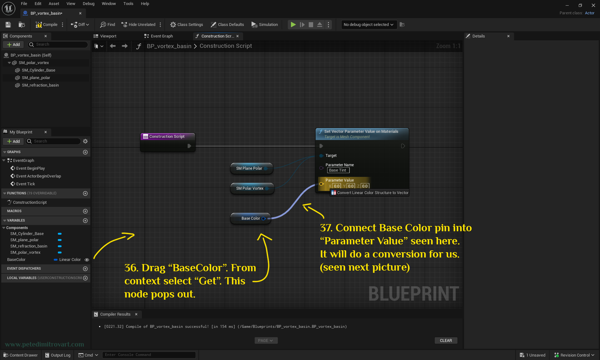
Everything should look like above after the new conversion pin (the one going from dark blue to dark orange and then connecting into “Parameter Value”).
Tip:
When we made our variable, instead of going for Linear Color we could have gone for Vector 3. That Vector 3 would have technically been a color - one with no alpha of course - that then directly connects above without needing a conversion node. When exposed, the Vector 3 would have X, Y and Z value and would not give us interface with a color picker, which is not ideal. Us using a Linear Color structure instead and then converting it to Vector 3 allows us to have a nice color picker which makes it more artist / user friendly. We will see that picker in action in a few pictures down this blog post.
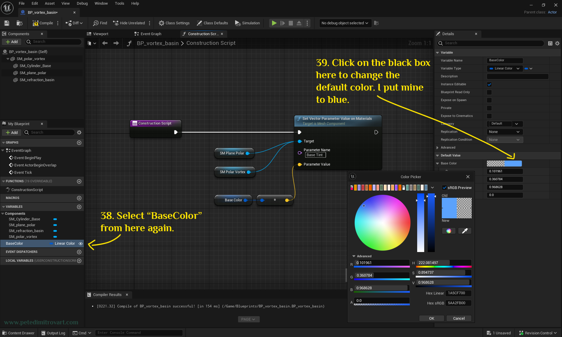
Select the “BaseColor” from here (the left side panel) again. Click on the black box on the right side panel to change the default color. I put mine to blue. That color picked seen here would not have worked had we not done it the way the green “Tip” box above describes.
We are done with the Blueprint set up!
In A Level
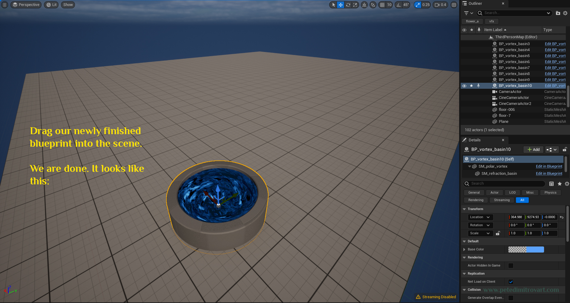
Drag our newly finished blueprint into the scene. It looks like this:
Now duplicate the newly placed blue vortex blueprint. Move it to the side. From the right “Details” menu of UE5 change the color (this is the Base Color variable that we implemented).
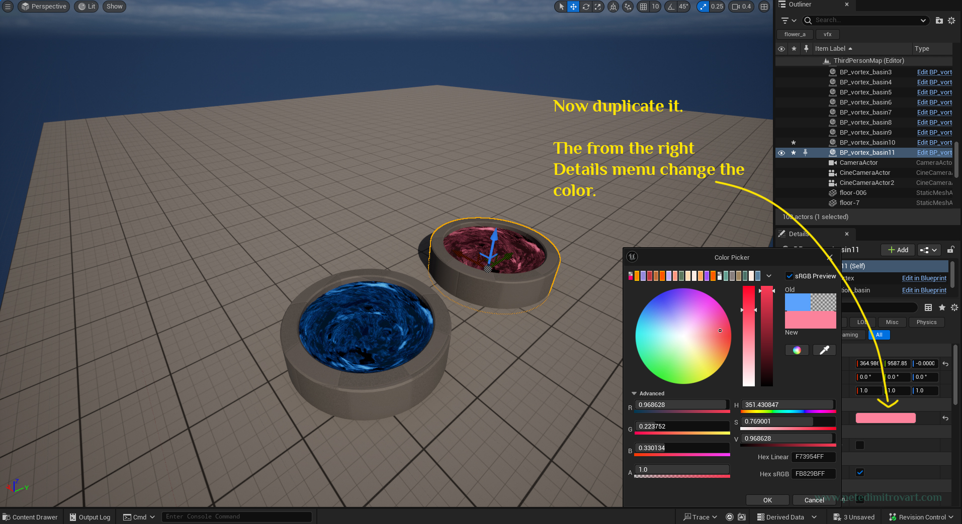
Duplicate your blueprint as many times. Set as many different colors you want. All of the materials are dynamic and are saved inside the level itself. As such our Project Directory is tidy and not overflowed with lots of material instances.
Color Previews
Here is one final view of our work.
Conclusion
In this optional part of the VFX tutorial for creating a vortex basin, we looked at Blueprint set ups. We learned how to bundle our few different static meshes so they are more artist friendly and efficient to use. We then looked into using construction script in order to connect a linear color blueprint parameter into the material used on the vortex. That allowed us to efficiently change the color of each unique vortex blueprint instance, once put in the world, without having to make unique material instances in our project directory.
I hope you enjoyed reading and going through this tutorial series. I had a lot of fun putting it together and I sincerely hope it comes to be useful and educational for anyone reading it out there.
It took me around a month and lots of hours after work to write this all up. It was a lot of effort to create all of the images, annotate them on top step by step, and give them alt text. I think we totalled to around 180 images. As such if you would like to drop a tip over at my Ko-fi page, I would be very grateful. You can find it in the blue badge link below. Alternatively you could purchase the asset itself from my shop.
Cheers,
Pete.
If you enjoyed this blog post, consider subscribing in the form below. That way you will get a notification the next time I publish a new blog.