Intro
Creating Refraction Material Shader in UE5.
After we created the Polar Coordinates / Circular Distortion material shader in the previous entry of this tutorial series, we will now add a secondary layer of detail on top.
That will be in the shape of a refraction effect that will sit above the polar coordinates material of the vortex.
If you are just now tuning in and would like to accomplish the visuals seen in the previews below, make sure to go over the previous entries:
Part One - Creating Static Geometry
Part Three - Making Polar Coordinates Shader
Software that we will be using:
- Unreal Engine 5
- Blender
- Substance Designer
Tip:
Like in the previous tutorial part, I will be creating the parent material in Unreal Engine 5. If your project is in Unreal Engine 4, you can still follow. The tutorial does not use any material graph nodes or features that are locked to UE5. Everything is available in UE4 as well.
If you are curious for the exact version of my engine, I will be using UE5.3. You can use any previous ones though, as already mentioned above.
Before we dive in, lets see the final preview of everything:
Videos Preview
(Youtube embedded video above, showcasing the final vortex VFX we will be creating.)
So far we’ve created the geometry, the textures and the moving, syphon-inwards material graph. Now we will create the refraction material to go on top.
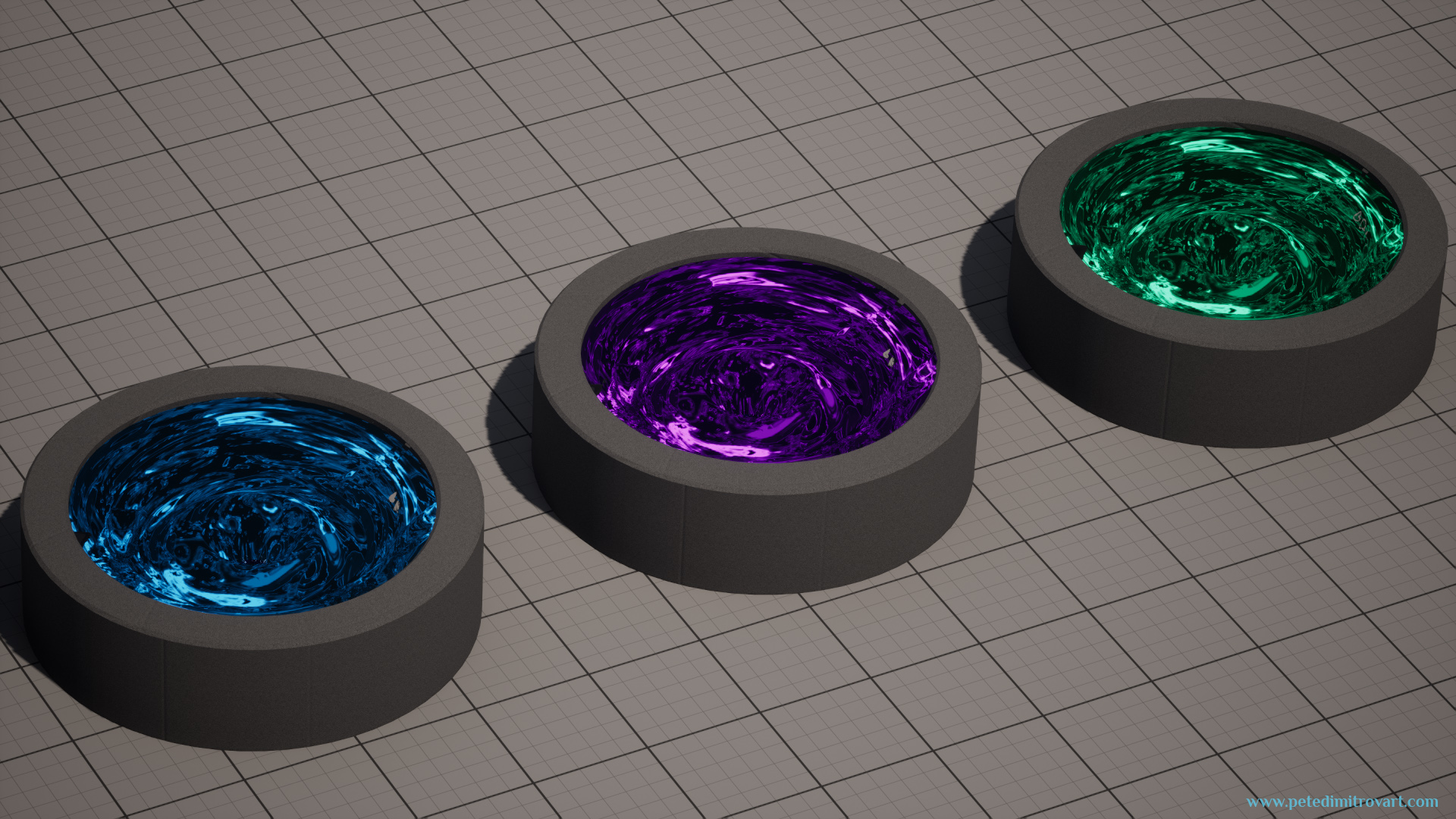
(Youtube embedded video above. Shows the VFX basin duplicated three times. One is blue, the other is purple, the last one is green.)
Screenshots Preview
Here are screenshot previews as well:
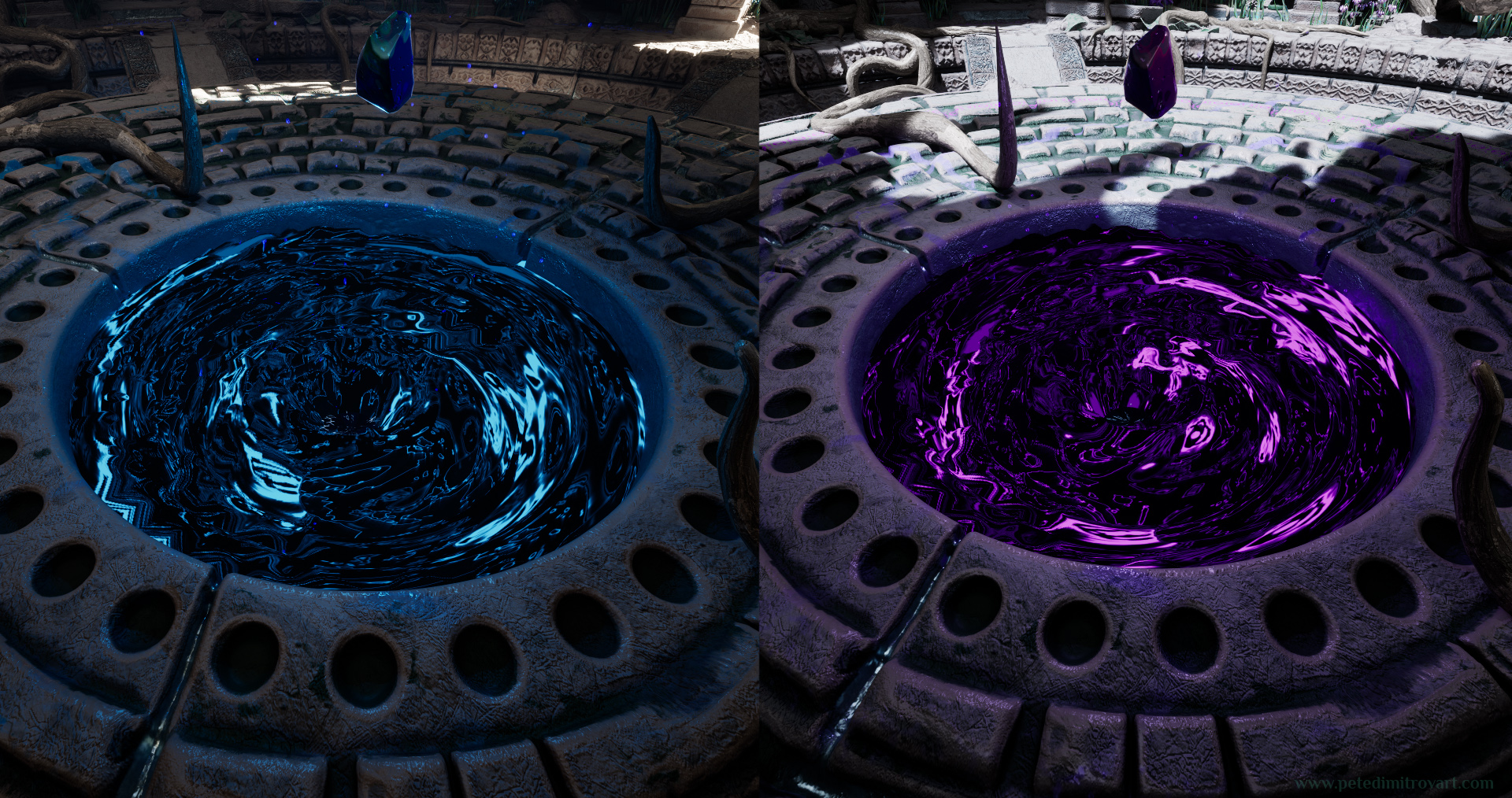
It’s been mentioned in the previous entries but we are making only the VFX. We are not creating the rest of the room or the art seen. If you wish, you can read about the creation process of the rest of the room here.
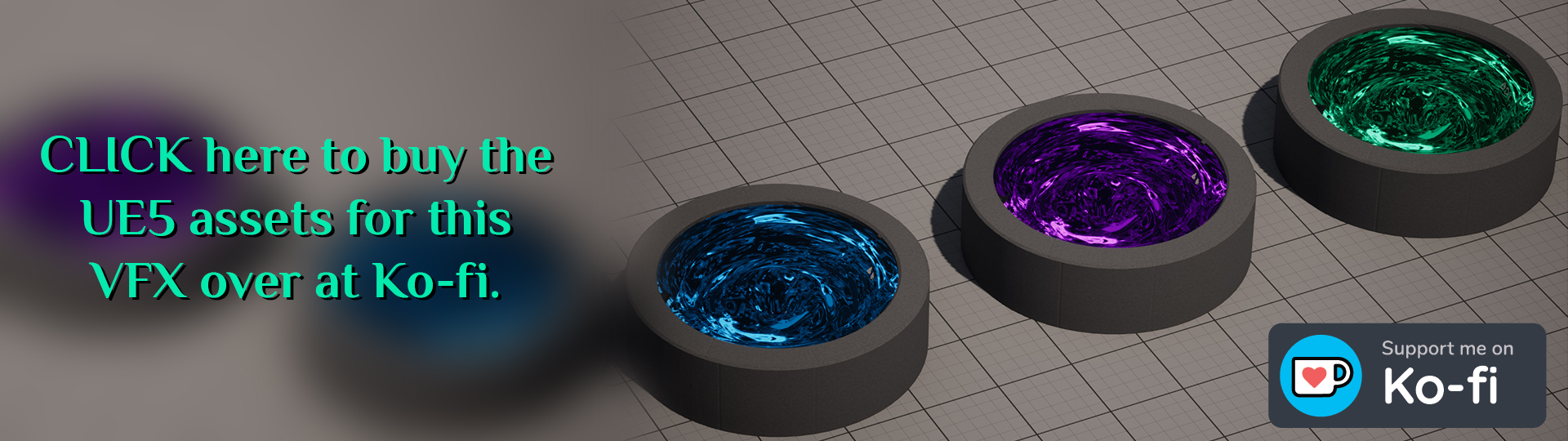
Get The Asset
If you would like to buy the work files behind this tutorial series, follow the link by clicking the image below.
Refraction Preview
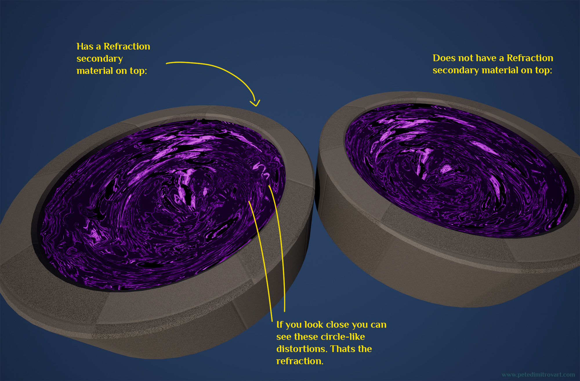
With the main visual already created - the circular vortex shader - we can now add another slice of detail to go on top. That will be in the shape of a refraction material that is mostly transparent. It will sit on a secondary copy of the base vortex basin static mesh. This copied static mesh will be moved slightly up in space so it floats.
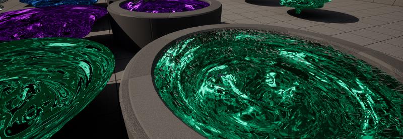
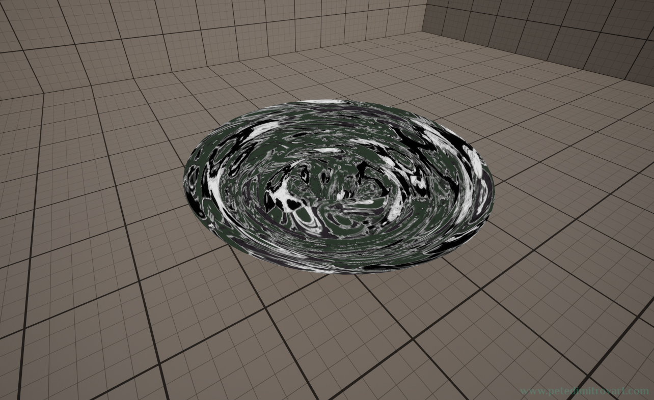
Looking at refraction is a bit hard in static screenshots. It’s an effect that is much more visible in movement. However, here is a screenshot where if you look closely in the upper right corner of the cylindrical basin of the green vortex, you can notice the refraction:
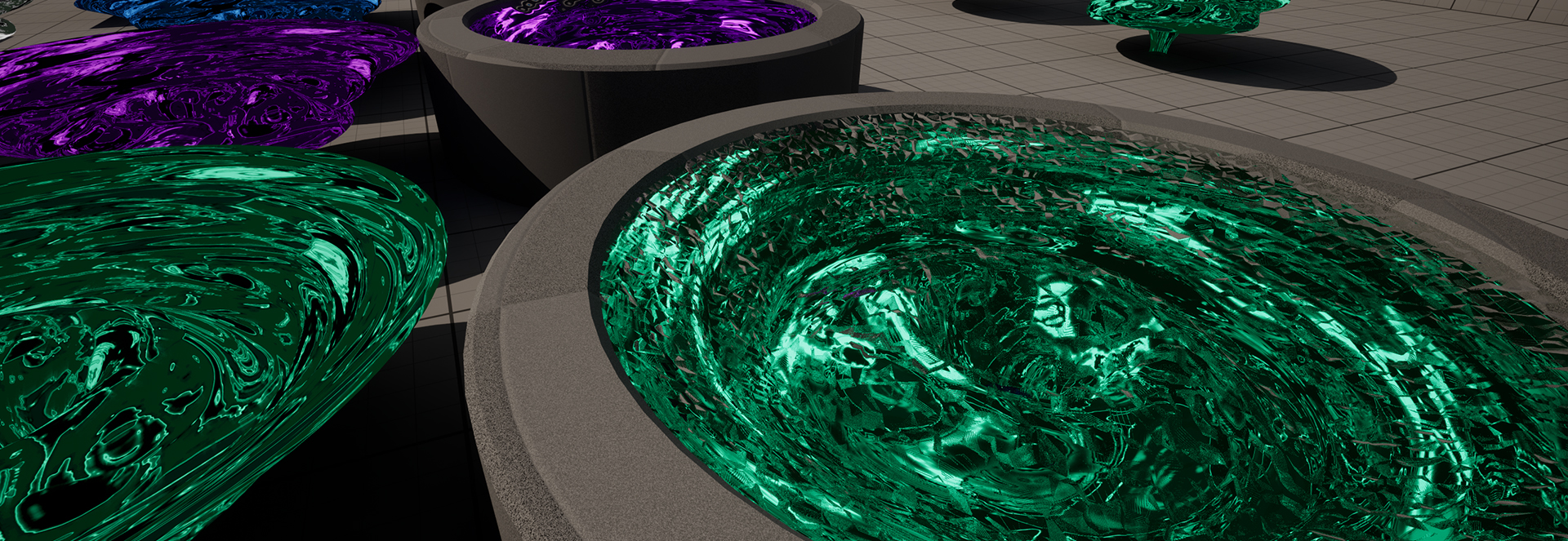
The refraction picks up colors from the rest of the scene. As such the warm gray color cells we see, above the green vortex, are not artifacts or transparent parts of the polar material. Instead its a refraction material put on a high value, picking up and refracting the rest of the scene.
It might look a bit odd, and perhaps ugly, from this close up, at this high value. I have put it to an intensity overly high just to showcase it. In our final result it will be much more subtle and work with the vortex in a much better way.
Here is a video cut, as seen by the end of this tutorial, that shows the same watery refraction in a way more visible (pay attention to the lower and middle left corner of the circular basin, that is where you can see it the most).
Material Graph Preview
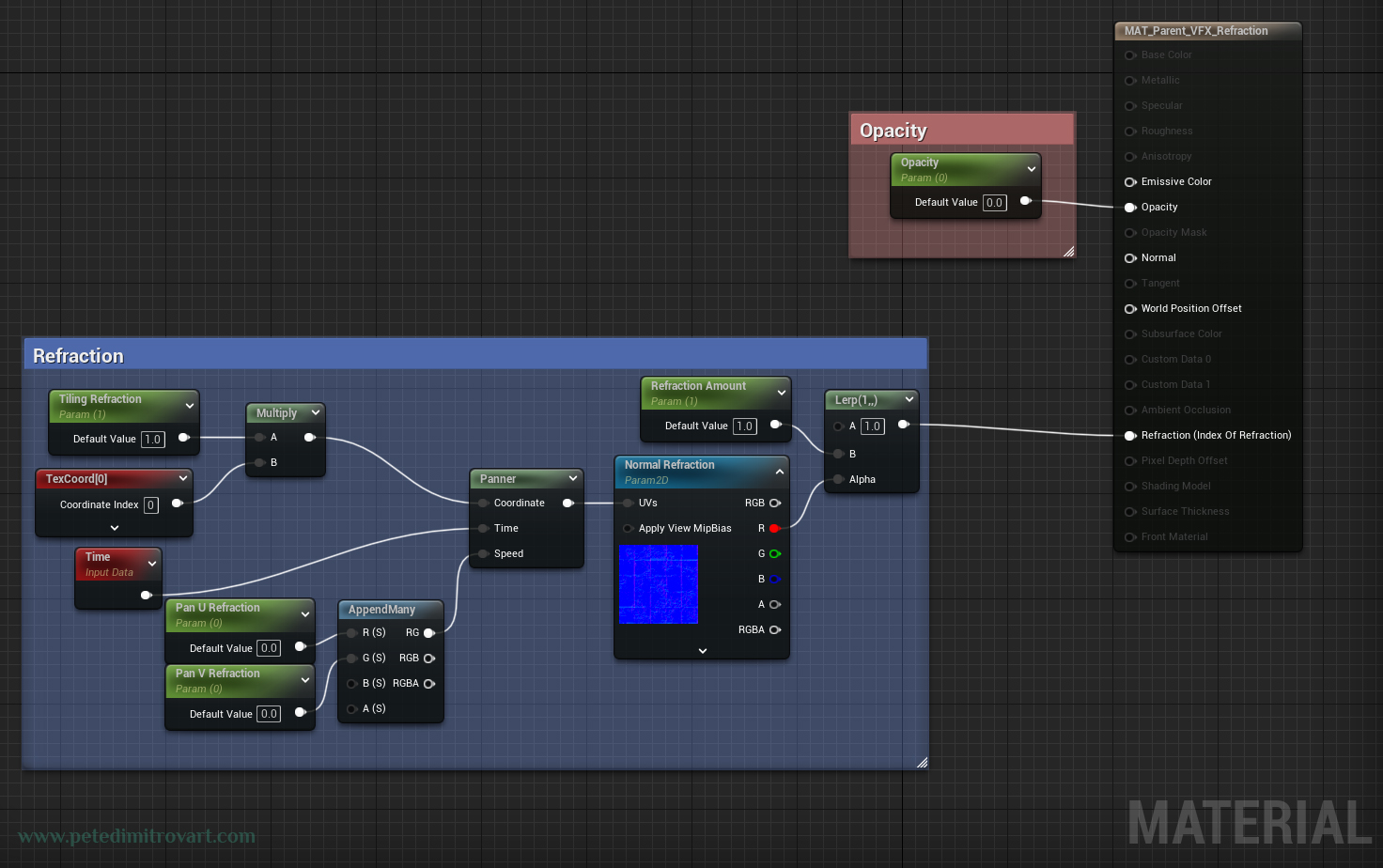
Before we get into creating the material graph, lets see all of it as a quick preview.
Note:
I have Pan U Refraction and Pan V Refraction scalars above. The ones going into the Panner node. I ended up not using those. You can either skip that part and have your TexCoord - Multiply - go directly into UVs of Normal Refraction, or you could follow and recreate it. I added them at first because I thought it might be useful to animate the refraction slightly in one direction. I ended up not using it. Perhaps you might want to try it and personalize your visual with it.
Creating the Refraction Graph
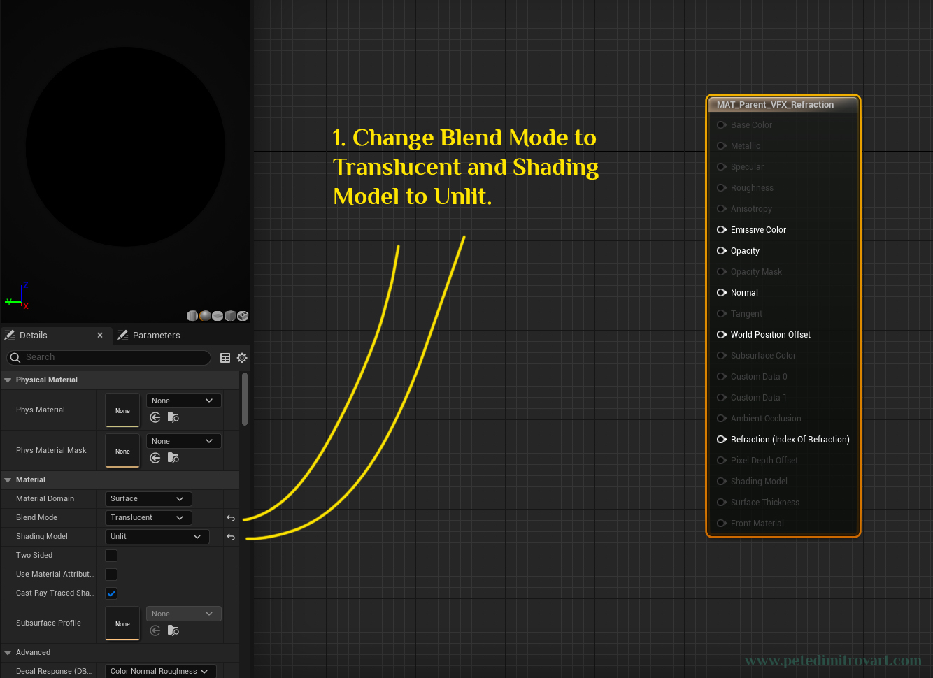
Navigate to the part of your Unreal Project Directory where you have a folder where you keep your Parent materials. Right click and create a new one. Name it “MAT_Parent_VFX_Refraction”. Open it.
Change “Blend Mode” to “Translucent” and the “Shading Model” to “Unlit”.
Tiling Refraction
Right click and search for a “Scalar Parameter” (or hold down “S” on the keyboard and press anywhere to instantly add one). Name it “Tiling Refraction”. Position it like below. Next search for “Texture Coordinates” and add one below the “Tiling Refraction”. Hold down “M” on the keyboard and then left mouse click anywhere on the screen to add a “Multiply” node. Connect the A of it into “Tiling Refraction” and the “B” into TexCoord[0].
![Material graph screenshot that shows a green node “Tiling Refraction”, a red node “TexCoord[0]” and a final “Multiply” in which everything is connected. Yellow text is transcribed in the paragraph above.](/p/amarantos-008-tut04/amarantos132.jpg)
Panner (Optional)
As mentioned in the yellow note box at the start of this article, this part for creating a moving panner is optional. You could skip it.
Search for “Time” and add it in here. Add two “Scalar Parameters” and name them “Pan U Refraction” and “Pan V Refraction”. After them add “AppendMany” node and Connect R and G of it as seen in the image below. (“Pan U Refraction” goes in “R” and “Pan V Refraction” goes in “G”)
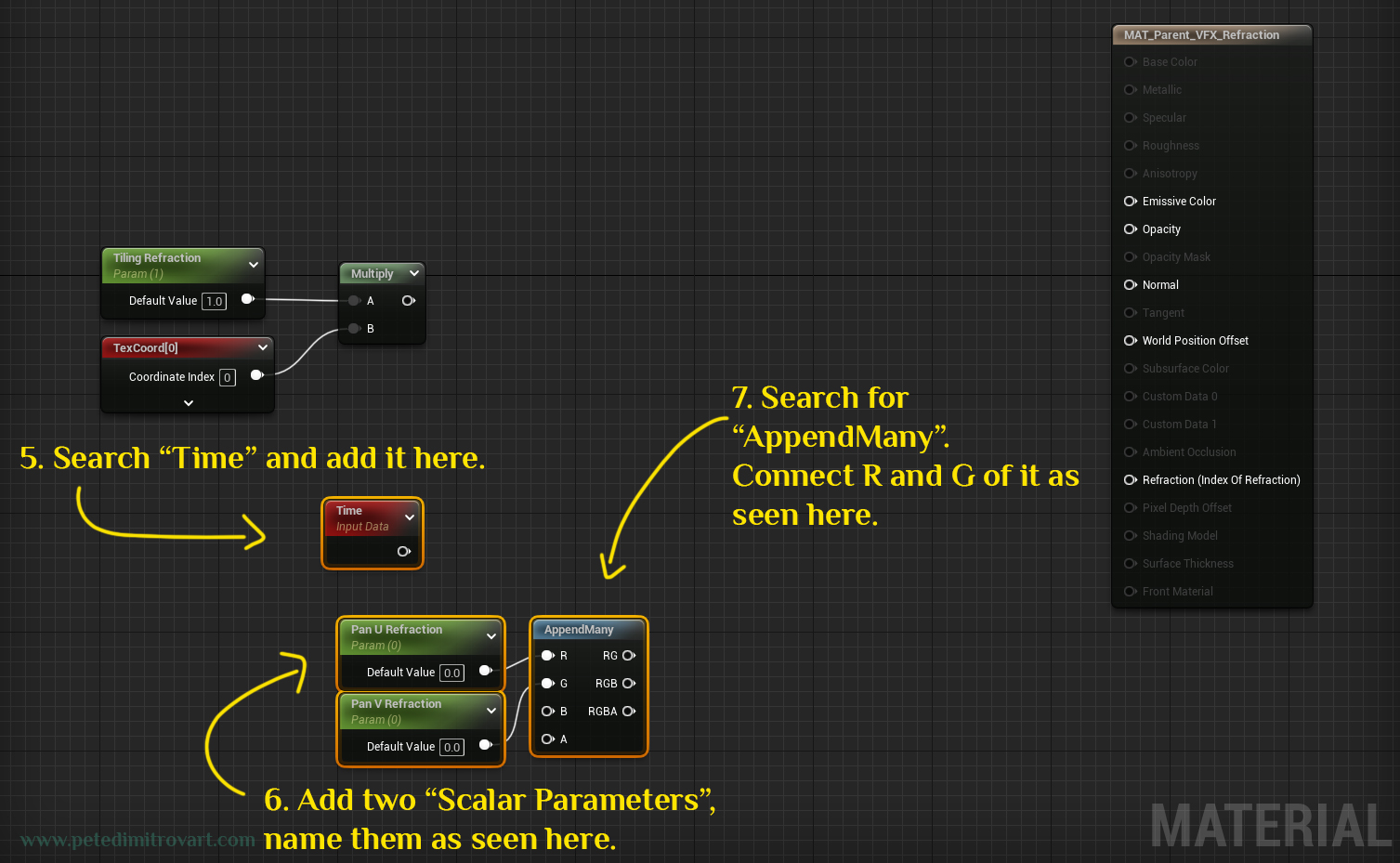
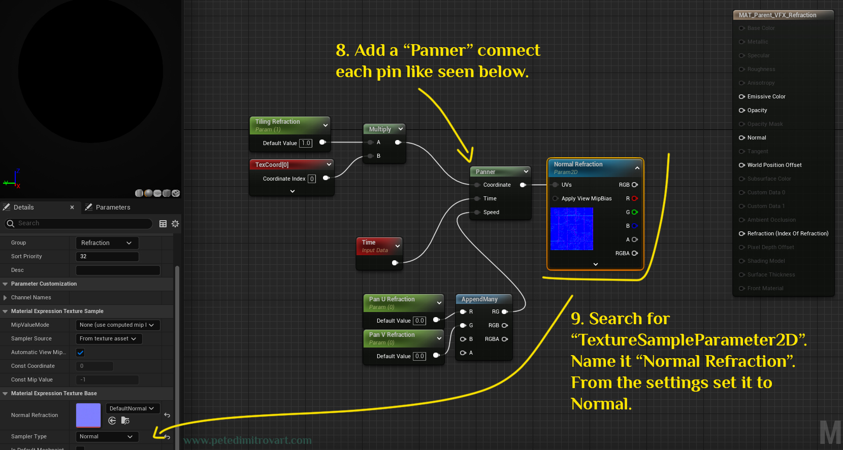
Add a “Panner” connect each pin like seen below. Search for “TextureSampleParameter2D”. Name it “Normal Refraction”. From the settings set it to Normal.
Refraction Amount and Lerp
Important:
We said that the above Panner with its Time and two scalar parameters are optional. The TextureSampleParameter2D that we renamed to Normal Refraction is not optional (its mandatory). We need that even if we skip adding Panner. If you skipped it, revisit the previous image.
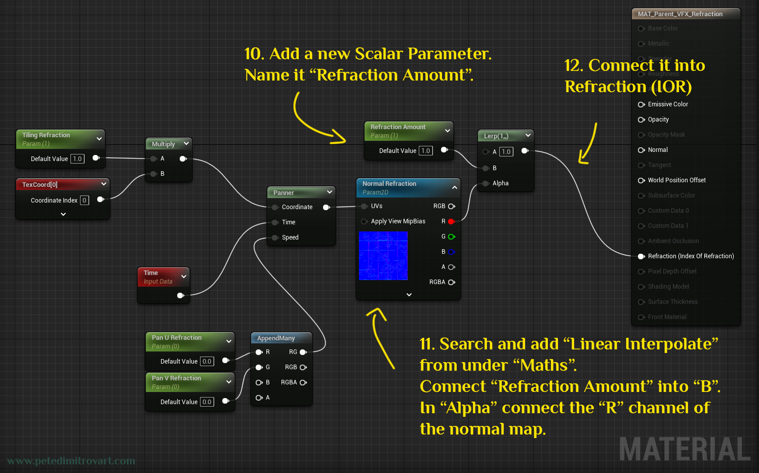
Add a new scalar parameter. Name it “Refraction Amount”. Search and add a “Linear Interpolate” from under “Maths” category. Connect “Refraction Amount” into the “B” of the Lerp. In its “Alpha” connect the “R” chanel of the normal map (Normal Refraction).
Connect all of it (the result of the Lerp) into the Refraction (IOR) in the final material input.
Frame and Tidy Up
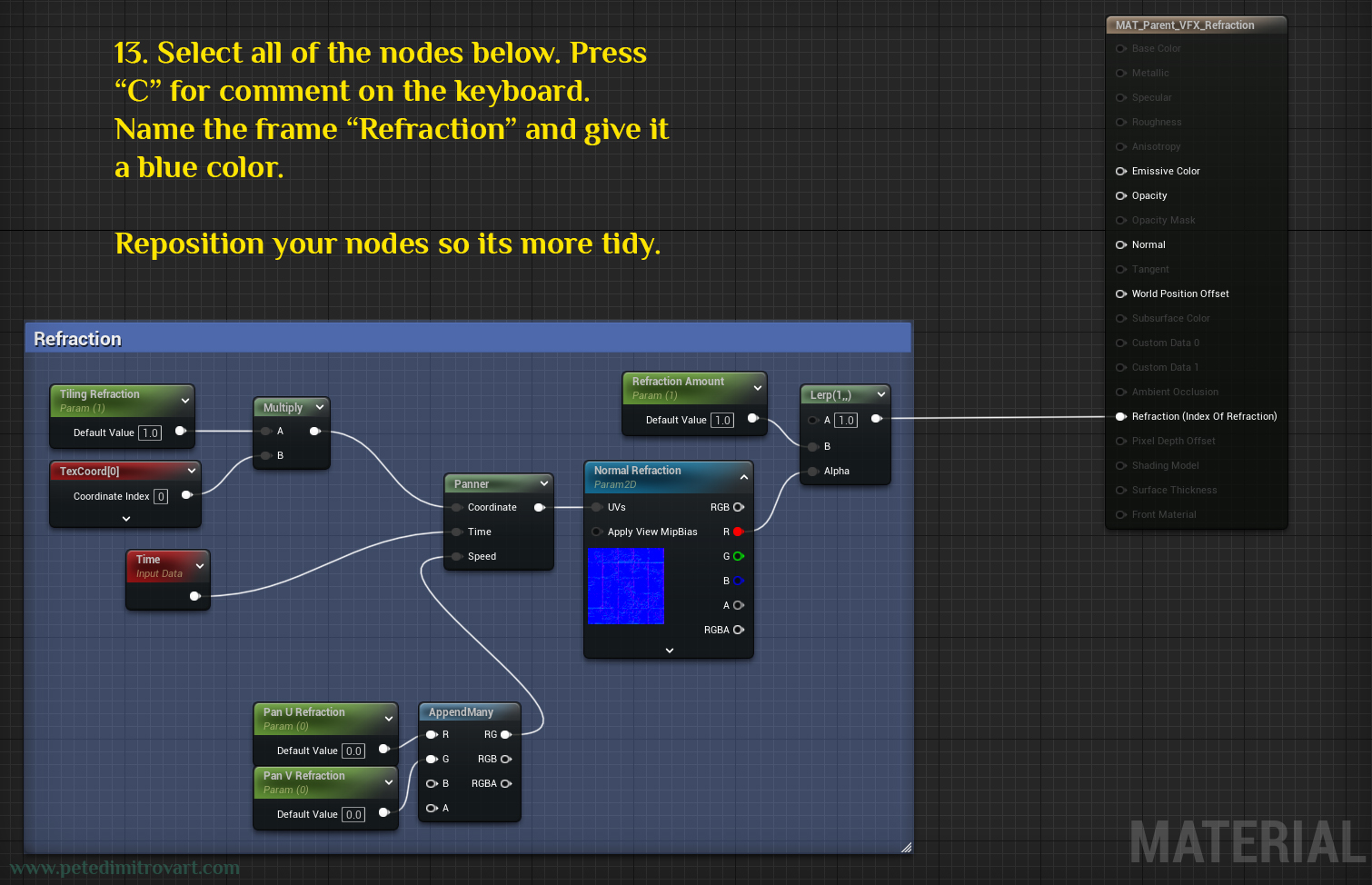
Select all of the nodes below. Press “C” for “comment” on the keyboard. Name the newly created frame “Refraction” and give it a blue color (or whatever color you like). Repositions your nodes inside so its more tidy.
Opacity
Final step.
Add a new “Scalar Parameter” and name it “Opacity”. Connect it into the “Opacity” of the end material input. If you wish, frame it with a comment in red color.
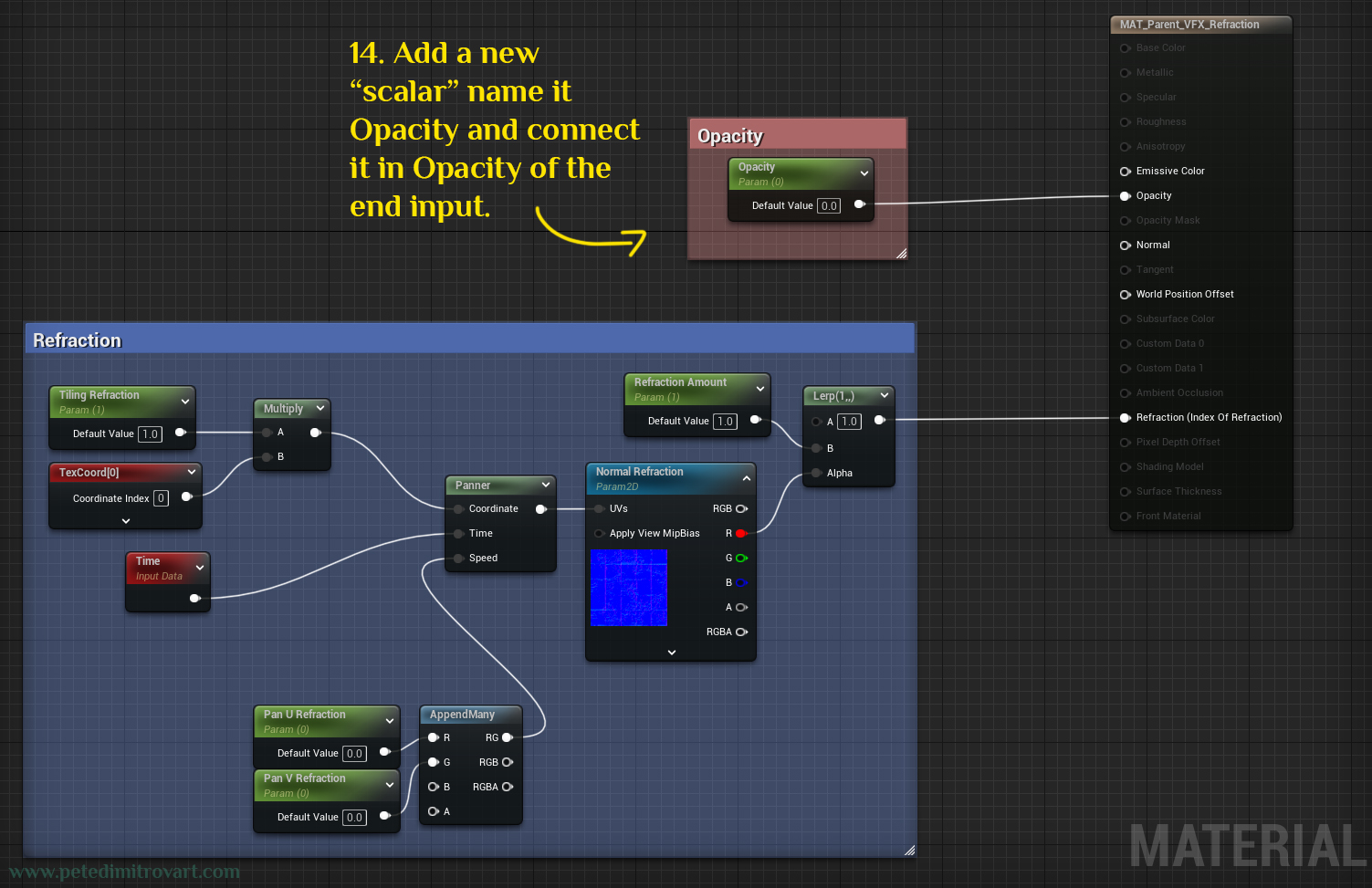
We are all done with that.
Material Instance
Go back to your “Content Browser” and find your parent material that we just created. The “MAT_Parent_VFX_Refraction”. Right click on the asset and from the new context menu select one of the top options that reads “Create Material Instance”.
Rename the resulting instance from “MAT_Parent_VFX_Refraction_Inst” to “MAT_VFX_Refraction_Inst_A”
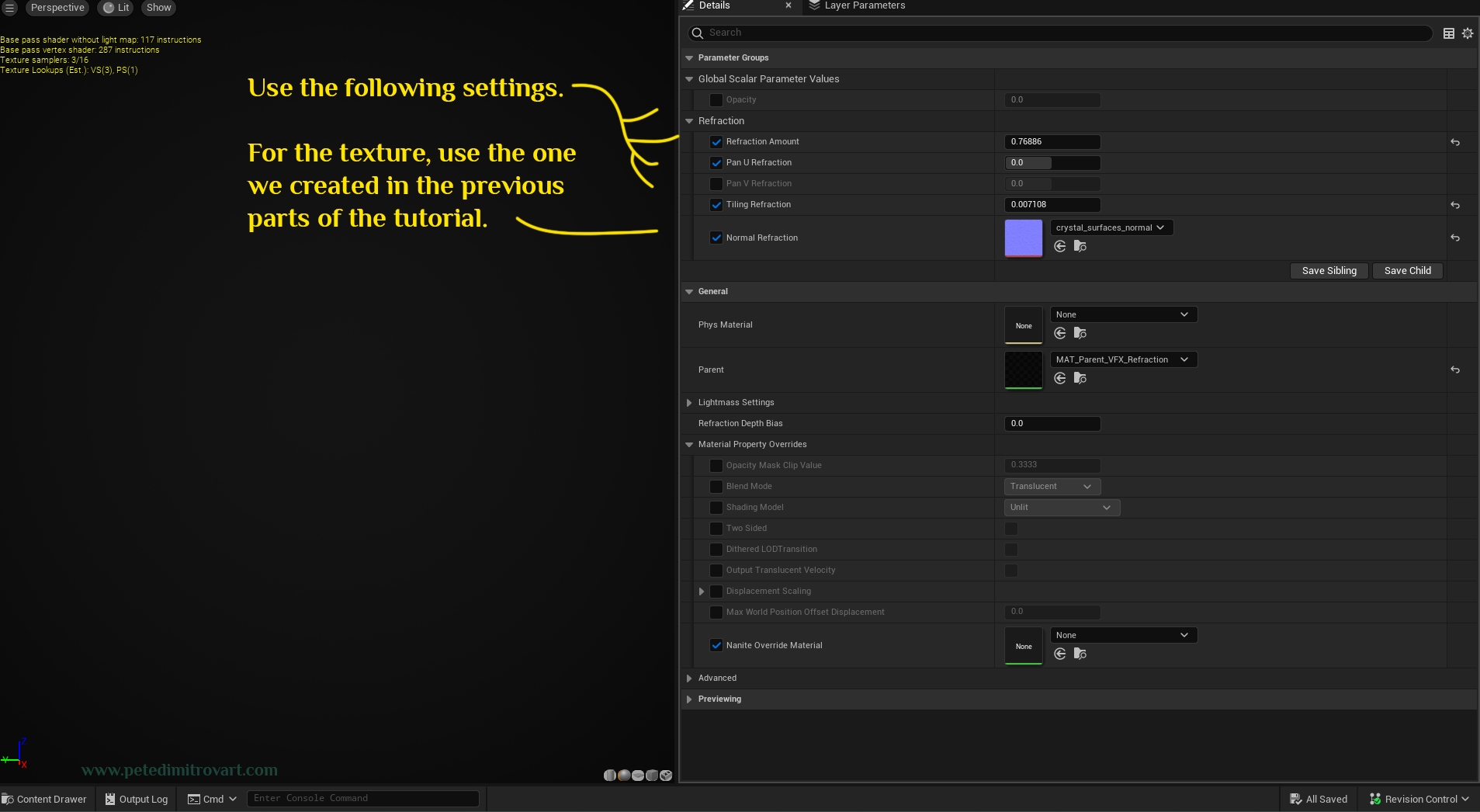
Use the following settings (yours might appear in a different order because we didn’t group them, but that is okay):
- Refraction Amount: 0.76886
- Pan U Refraction: 0
- Pan V Refraction: 0
- Tiling Refraction: 0.007108
- Normal Refraction (texture): crystal_surfaces_normal
The final one, the texture, is this one which you should have imported in your project already:
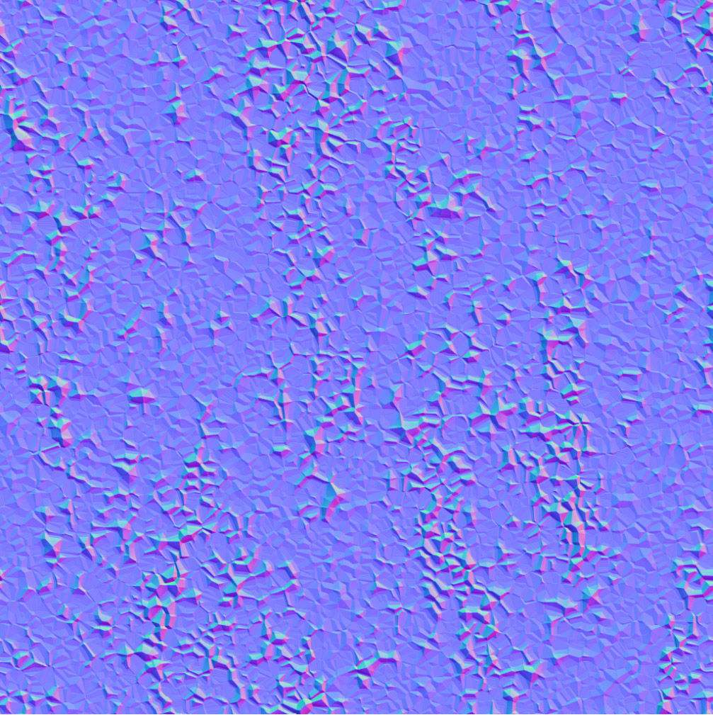
But if you don’t have it, then you can revisit the second tutorial of this series where we create the texture in Substance Designer. Find it over here “Part Two - Creating The Necessary Textures”.
Applying The Material on a Mesh
Lets go back in an open scene where we have placed the vortex mesh basin and the polar coordinates material on it, as seen in the previous tutorial step - “Part Three - Making Polar Coordinates Shader in UE5.”.
It should look like this (below). Im focusing on a version not tinted in blue, purple or green, but you can focus on whichever you like.
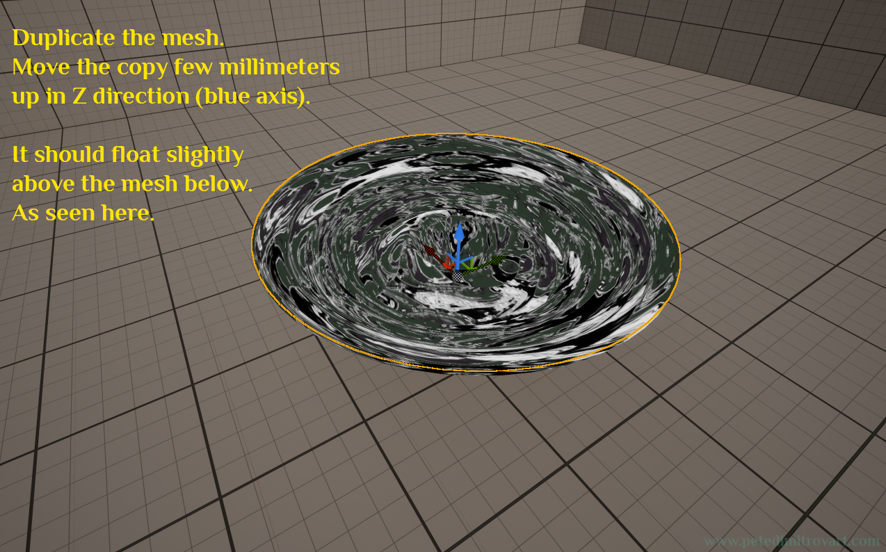
Duplicate the mesh. Move the new copy a few millimeters up in Z direction (thats on the blue axis). It should float slightly above the old mesh seen below. It should all look a bit like the image below.
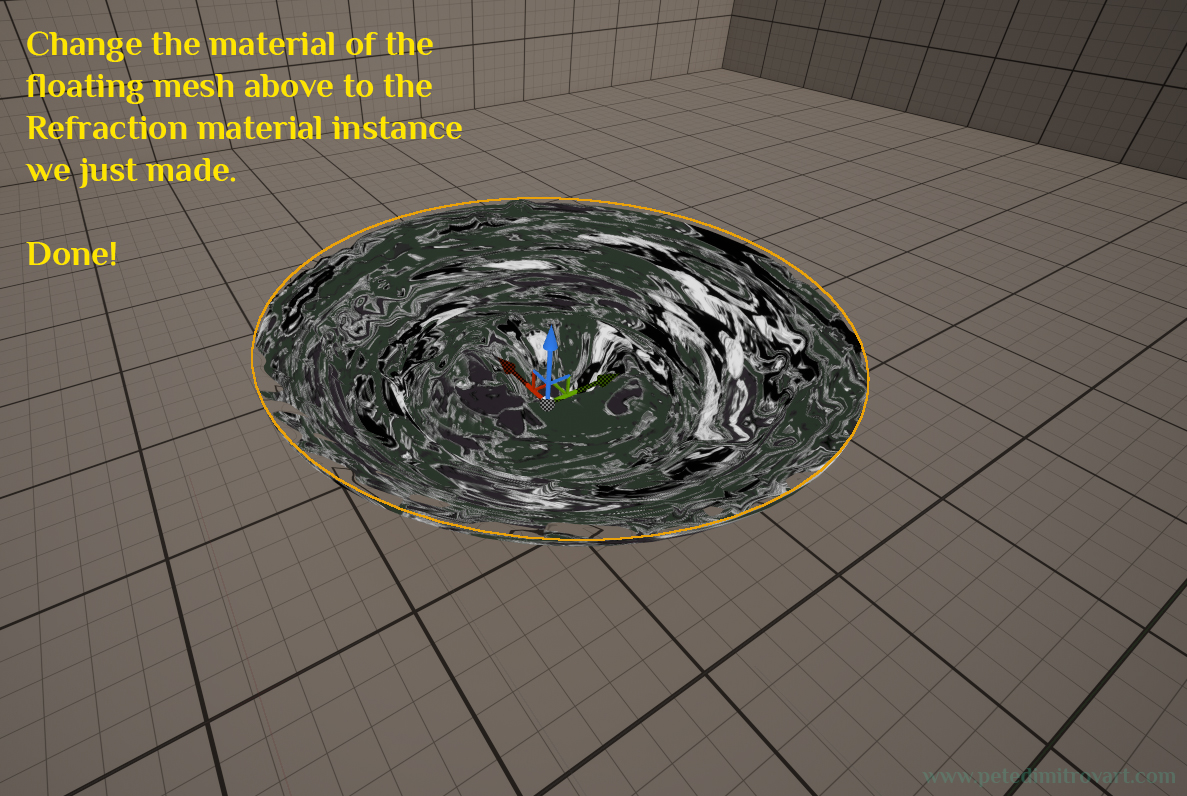
Change the material of the floating mesh above to the “Refraction” material instance we just made (that is “MAT_VFX_Refraction_Inst_A”).
As a final step I went into Blender and made myself a hollow cylinder that is near the diameter of the vortex static mesh and protrudes outwards - that makes it a frame. I put that around my VFX to give it a finalized appearance and have it sit more like a hole or a well.
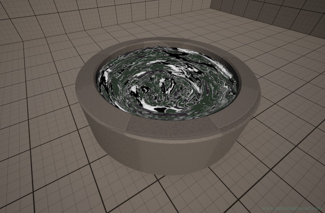
I won’t cover the making of this cylinder because I trust you could make one yourself. If you don’t want to go out of UE5 and into Maya or Blender, you could perhaps make your cylinder straight into UE5 using the Basic Brush geometry.
Troubleshooting
If you look straight from above, you will see that in the dead middle of the basin, there is UV distortion that breaks the visuals a bit.
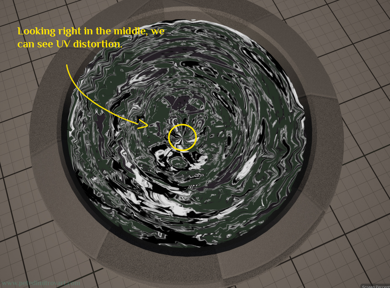
I could revisit the mesh and try to fix this in Blender, but I have a quicker and easier way that could potential look better.
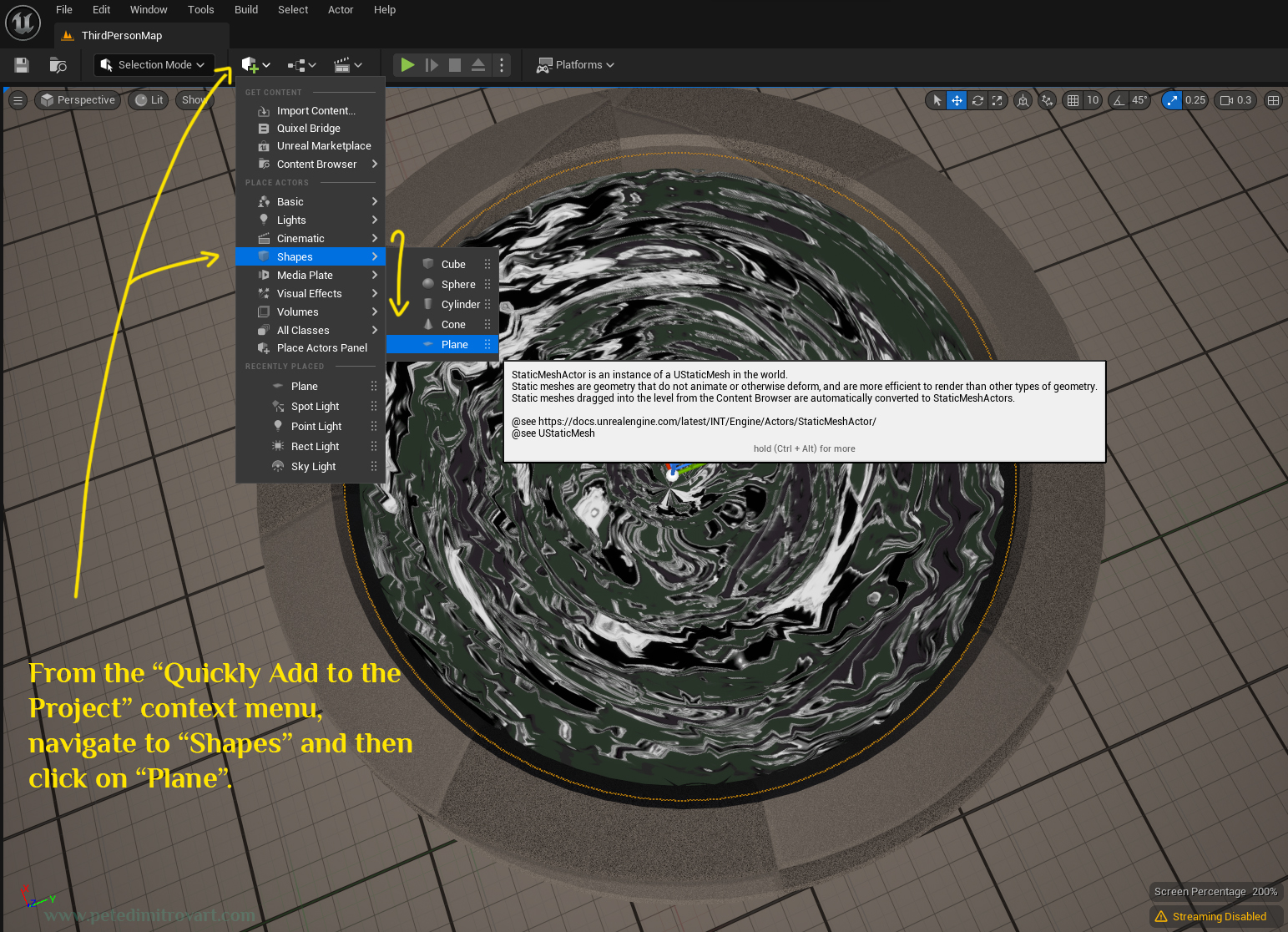
From the “Quickly Add To The Project” context menu, navigate to “Shapes” and then click on “Plane” to add one.
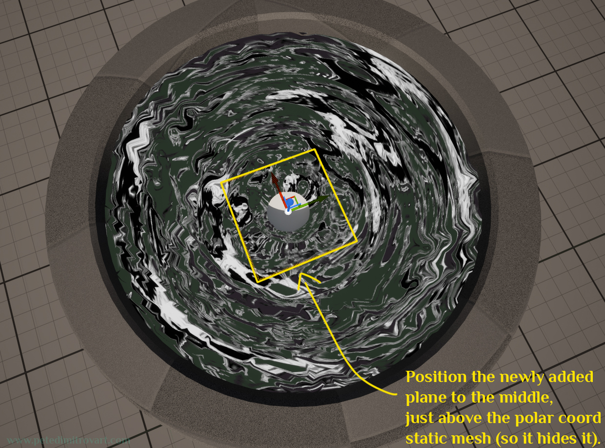
Position the newly added plane to the middle. It should sit just above the polar coordinates static mesh (so it hides the issue we have).
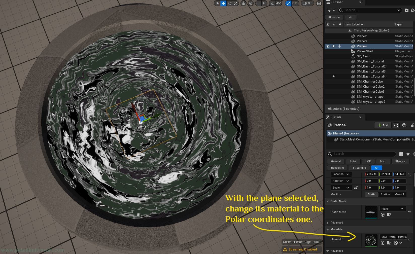
With the plane selected, change its material to the Polar Coordinates one.
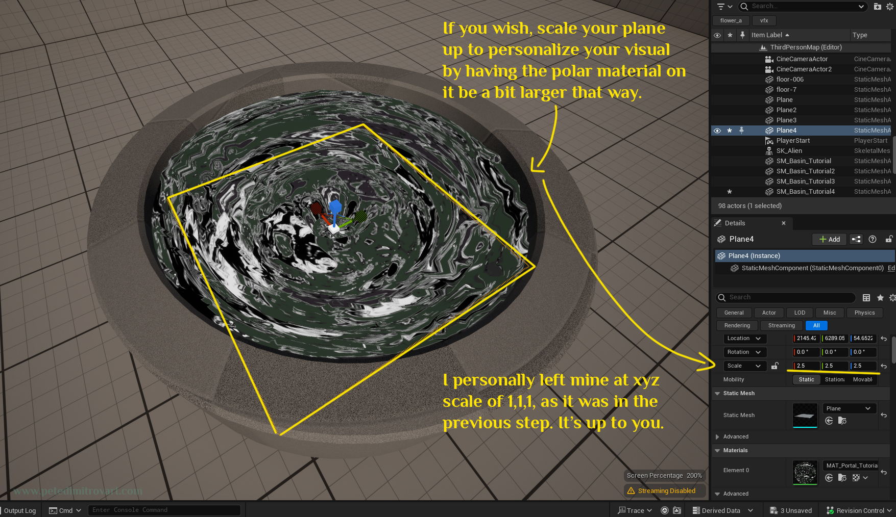
If you wish, scale your plane up to personalize your visual by having the polar material on it be a bit larger that way. I personally left mine at xyz scale of 1,1,1 as it was seen in the previous step. It’s up to you. Just make sure if you scale it up to not have it go outside of the hollow cylinder, breaking the illusion and clipping outside.
All done! Congrats on following through with this tutorial.
Final Result
Here is a video preview of our final result. Congrats.
Conclusion
In this final step of the tutorial series we went over creating a refraction material graph shader. We then applied that on a mesh that sits a few millimeters above our previous static mesh basin, giving it a secondary level of detail.
With this tutorial we wrap up all visuals work on this. In the next, optional part, we will look over Blueprints functionality in UE5 / UE4 and how we can create an Actor that lets us change the color tint per instance basis, when used in the world.
If you’ve made yourself a VFX basin and picked a color tint you like, you can skip this next part. If you, however, wish to learn more about good practices with Blueprint Actors and how to use Construction Scripts in order to create more powerful set dressing actors, stick around for the next one.
Next part in the tutorial - Improving the efficiency of our work through Blueprints and Constructions Scripts.
Cheers,
Pete.
If you enjoyed this blog post, consider subscribing in the form below. That way you will get a notification the next time I publish a new blog.