Intro
This blog entry will be a bit different from the previous ones in “The Amarantos Ritual”. Instead of an overview and writing about my creative process, this one is a step-by-step guide. It is a written tutorial about how to create an Unreal 5 material shader VFX. It also will go over how to create geometry needed by the VFX idea and how to create some quick textured noises in Substance Designer. The textures are one of the driving forces in the VFX.
Software that we will be using:
- Unreal Engine 5
- Blender
- Substance Designer
Tip:
If you prefer Maya or 3Ds Max over Blender, then you could replicate the steps I take in your modelling package of choice and create the mesh we will need.
We will use Unreal Engine 5. However, we will not use any new or locked to UE5 features. If you are working in Unreal Engine 4, you could easily follow and replicate anything you see here.
Without further ado, lets dive in.
Videos Preview
Before getting into the steps of creating the VFX, lets take a look at a quick preview. It will show us what we are about to create.
(Youtube embedded video above, showcasing the final vortex VFX we will be creating.)
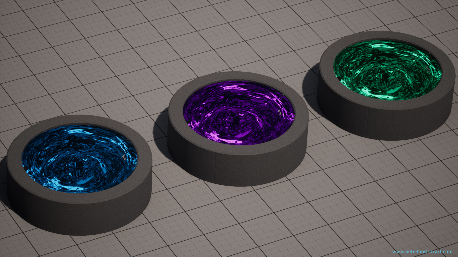
The material shader we will create will allow us to reuse every piece we’ve made and derive different colors:
(Youtube embedded video above. Shows the VFX basin duplicated three times. One is blue, the other is purple, the last one is green.)
Screenshots Preview
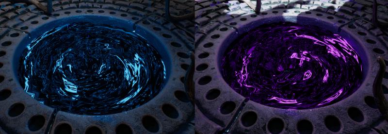
Here are some screenshot previews, showing the VFX in static images.
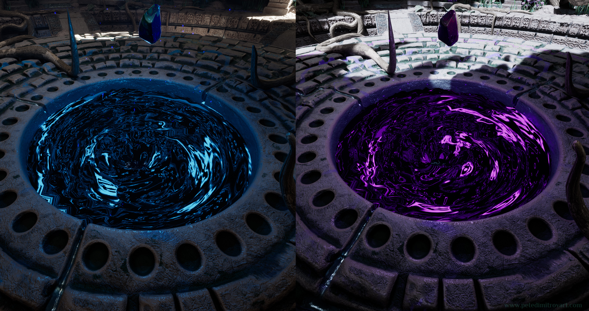
This tutorial will cover how to create only the vortex itself. It will not look at how to make the sculpture, stone basin that the VFX sits in. It will also not look at the making of any other art elements seen above.
If you are curious how the environment room was created and then how the crystals shaped to existence, you can do so by reading my previous entries in the blog series. You can do so over here.
If you like the VFX and you are not here for learning, but instead would wish to purchase the UE5 assets, follow the link by clicking the image below.
Pieces Necessary
The necessary pieces we will need and see how to create in this tutorial are:
- 1x Static mesh - this is a torus shaped into a basin.
- 1x “Polar Coordinates” material shader - this is the black and blue material that pans inwards, creating a “vortex” effect.
- 1x Refraction material shader - material using a tiled normal map that refracts light and sits on top of the main vortex as a secondary slice of detail.
- 3x Texture noises. One for masking things (linear, black and white). Another for the black and blue liquid visual (this acts bit like an albedo). Then a final normal map that has crystal-like distortions and when tiled the correct amount gives the refraction shader its appearance.
Lets begin with first creating the Static Meshes needed for the VFX.
Base Shape
Before we dive into any detailed steps about how to create the geometry, lets first see the final result:
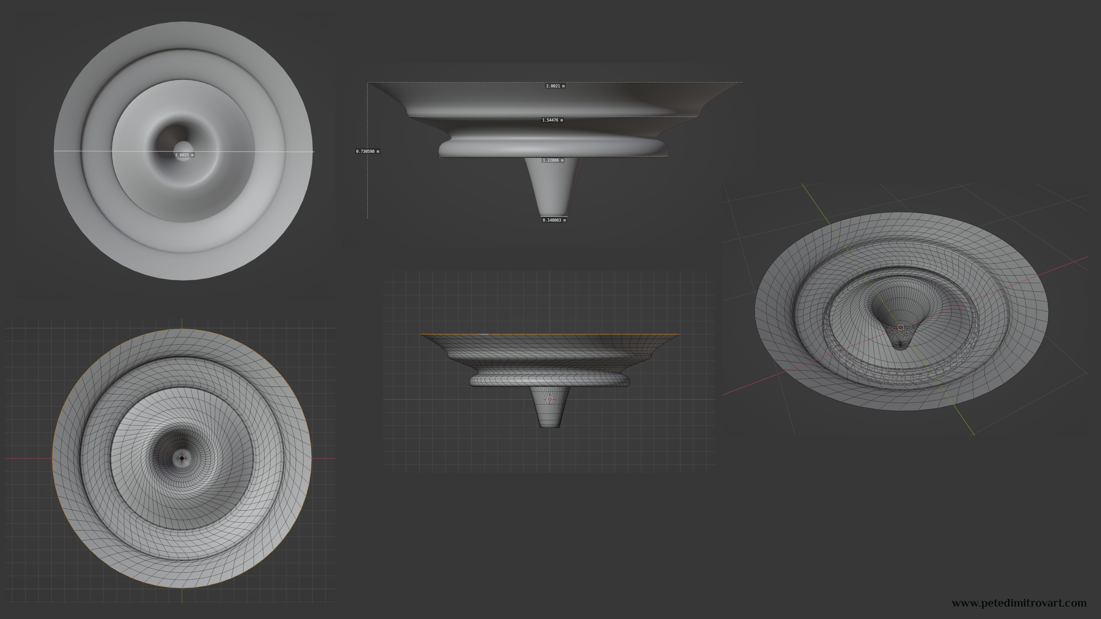
In the following guide we will recreate the geo seen above.
The vortex basin above has two key metrics: its wide 2 meters and its tall around 0.75 meters. As it goes downwards in space, its diameter of 2 meters shrinks to 1.5 meter then to 1.2 m then to a final 0.15 meters. The numbers above in the image have floating points but you can stick to the round numbers mentioned just now. The mesh is UV mapped without any seams (planar top-view mapping). Any slight distortion in the islands due to that will not be a problem and will instead help our VFX final result.
(You can inspect the UVs in step 5.13, seen right by the end of this page.)
If you are an intermediate to advanced 3D modeller, don't feel obliged to follow the next steps. By looking at the wireframe mesh above, you could recreate a similar results of your own, however you wish. For the VFX basin to look like the final results you don't need to constrain yourself to a carbon copy geometry. You could put your own touch of tweaks and personalizations on your geometry and still get an awesome result. If that is the case, skip through all of the Blender steps below.
As mentioned above, if you wish to skip the geometry guide, and have created something of your own, head to this link “The Amarantos Ritual - 06 - Vortex VFX Tutorial - Part Two” for the next part in this VFX tutorial series.
Step One
Start by opening a new Blender scene and pressing SHIFT + A to create a new primitive shape. From the drop-down menu, pick a Cylinder:
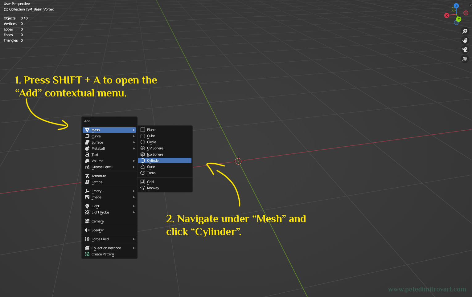
After adding a cylinder, in the lower, left corner of the screen we will get options to pick the features of the cylinder primitive:
Step Two
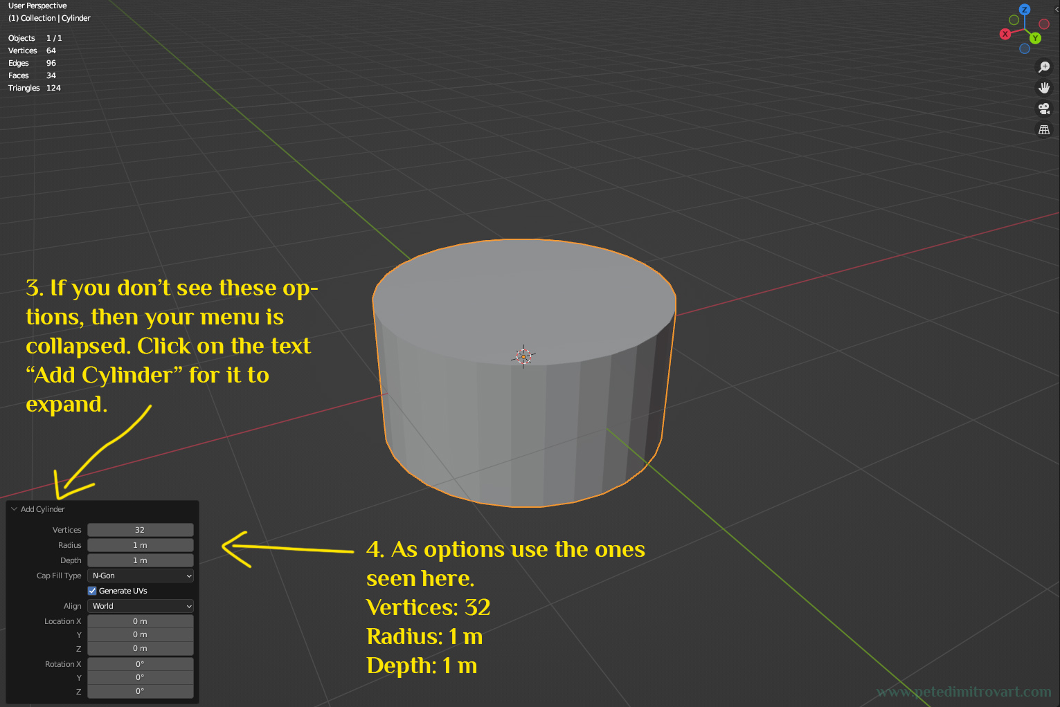
If a large context menu for “Add Cylinder” like above doesn’t immediately show for you, then make sure to look for a small bar menu going by the same name, hidden in that same lower left corner. Clicking on it will expand you the settings seen in the image above.
Most of the settings we can ignore. The important ones are “Vertices: 32” and “Radius: 1 m”.
The “Depth 1 m” is not particularly important because in the next step we will actually remove any edge loops that make up the outer ring faces of the cylinder. As such its depth will be removed.
Step Three
Next, press anywhere on the cylinder with the left mouse button. Then hit TAB on your keyboard to go into “Edit Mode” (or perhaps you have yours set to ALT+E as a shortcut.)
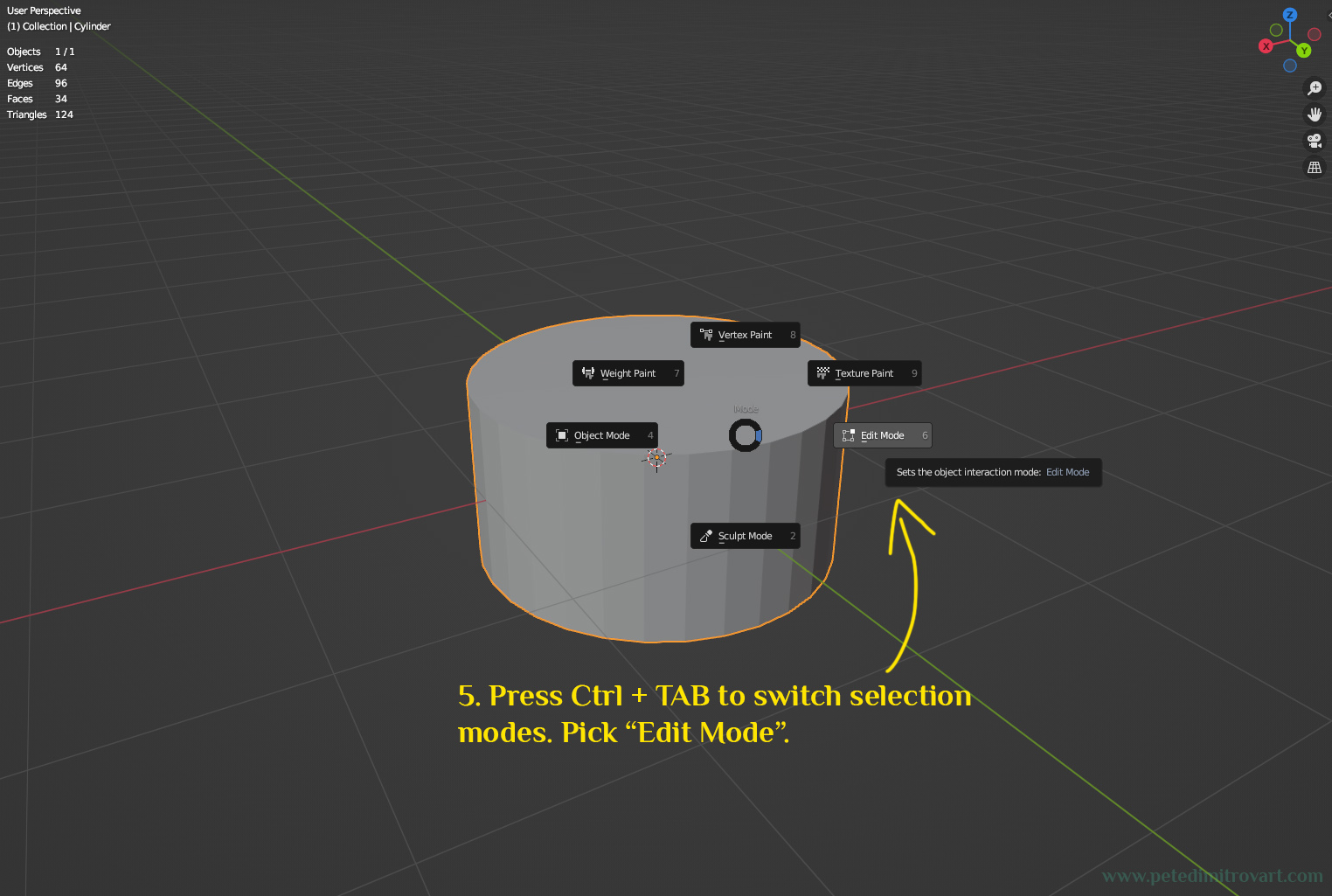
The goal here is to switch from “Object Mode” and go into “Edit Mode”. If neither TAB or ALT+E work for you, then try with the contextual radial menu seen and described in the picture above.
Step Four
Once you are in “Edit Mode”, select all faces, everywhere, while keeping only the very top circle face deselected.
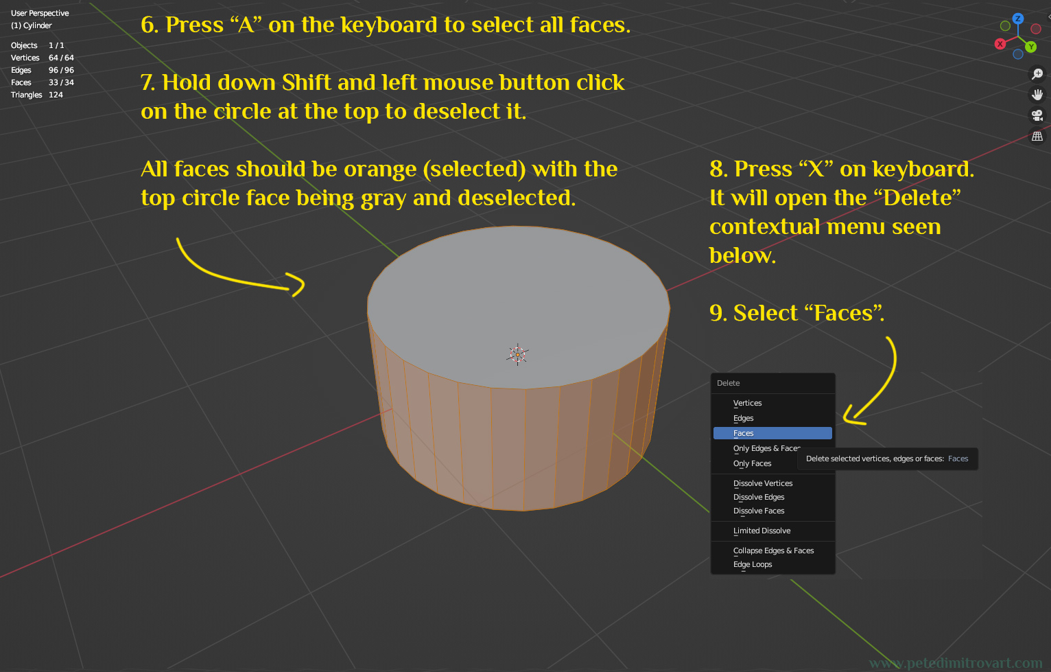
As the image above describes, press “A” on the keyboard to select all faces. Then hold down Shift on keyboard and left mouse button click on the circle at the top to deselect it.
Next press “X” on the keyboard. It will open the “Delete” contextual menu. From that dropdown menu select “Faces” to delete.
There are lots of ways to select the faces whilst only leaving the top circle deselected. Do whichever way you like and don't feel obliged to follow the description above as to how to accomplish it. If you wish, select each face one by one with the mouse whilst holding shift. Or instead select by big face loops, by holding ALT and clicking on the outer edge of a face, the edge facing the direction you want to mass select a loop.
Step Five
Now that you have deleted all of the outer wall faces and the bottom face, we are left only with the top circle face.
Select it. Then press “I” to “Inset Faces”. Click anywhere on the screen to have the lower left corner contextual menu for “Inset” appear (seen and described in the image below).
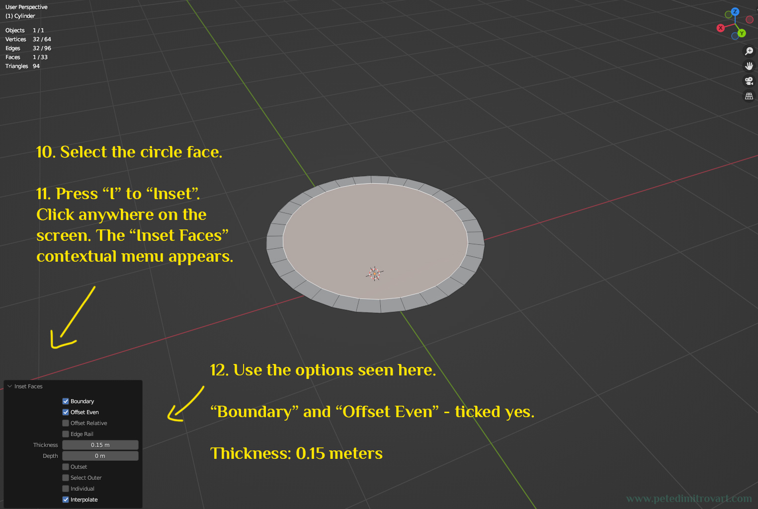
From the “Inset Faces” menu, select a Thickness of 0.15 m.
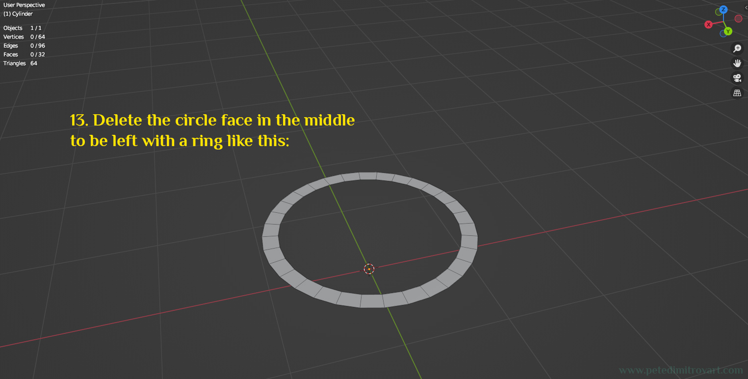
Next, select the circle in the middle and press “X” to “Delete Face” and be left with an outer ring like this:
Step Six
Select the inside loop of edges (marked in orange below). Move them down in Z direction to get this:
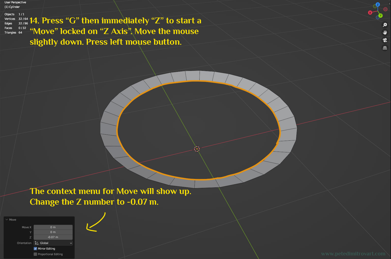
As mentioned above, press “G” on the keyboard. That will start a “Move” command. If you follow up immediately by pressing “Z” you will lock the movement onto that axis. Move the mouse slightly down. Then press anywhere on the screen in order to get the “Move” contextual menu show up. In that put in -0.07 m as a setting for Z.
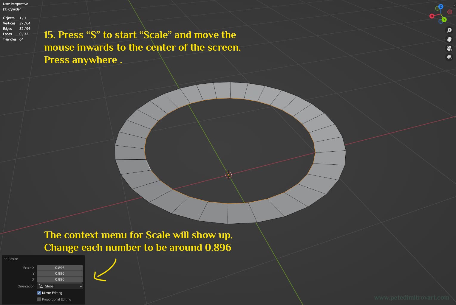
With that same edge loop selected, press “S” to scale down. Move the mouse to do any amount, then let go (press left mouse button). Once the Resize (scale) context menu shows up, put in X,Y and Z an uniform number: 0.896.
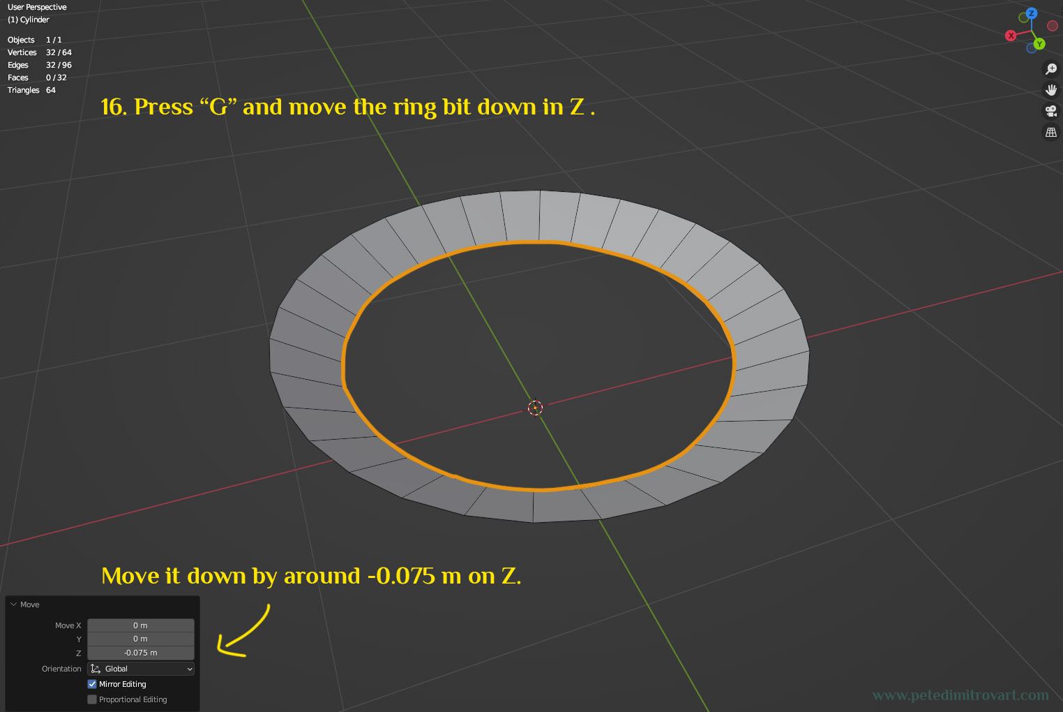
As described in the image above, use “G” to move the edge loop again. This time around move it down in Z by -0.075m.
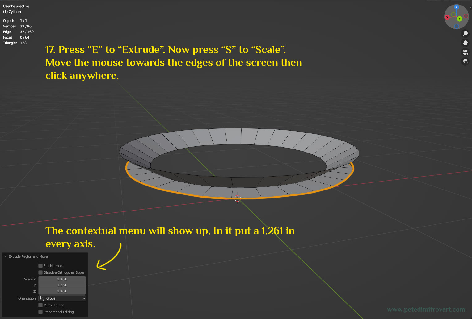
Image above: Press “E” to “Extrude”. Immediately press “S” to “Scale” Move the mouse out and click on the screen again. In the lower left corner context menu, put in 1.261 in X, Y and Z axis.
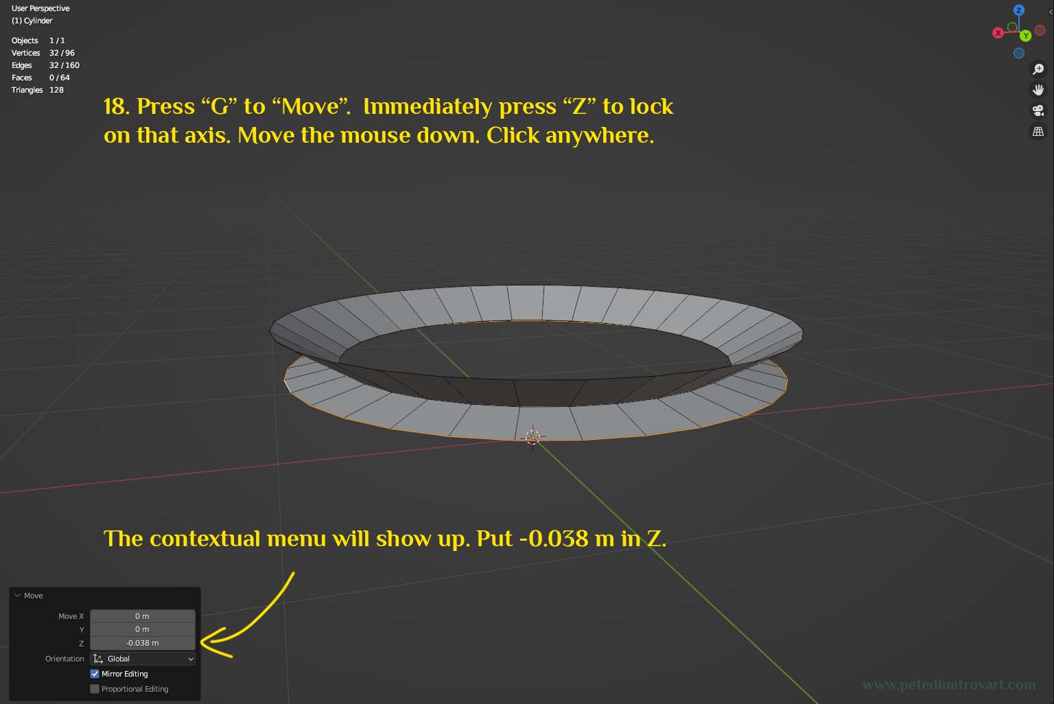
Image above: Press “G” to move. Immediately press “Z” to lock on that axis. Move the mouse down and click anywhere. In the context menu that shows up, put -0.038 in Z axis.
Step Seven
Rotate your camera slightly down so you see the mesh from the side. Press “E” to “Extrude”. Immediately press “S” to Scale down the newly made extrusion.
In the context menu that will show up, use uniform 0.806 as a scale down factor.
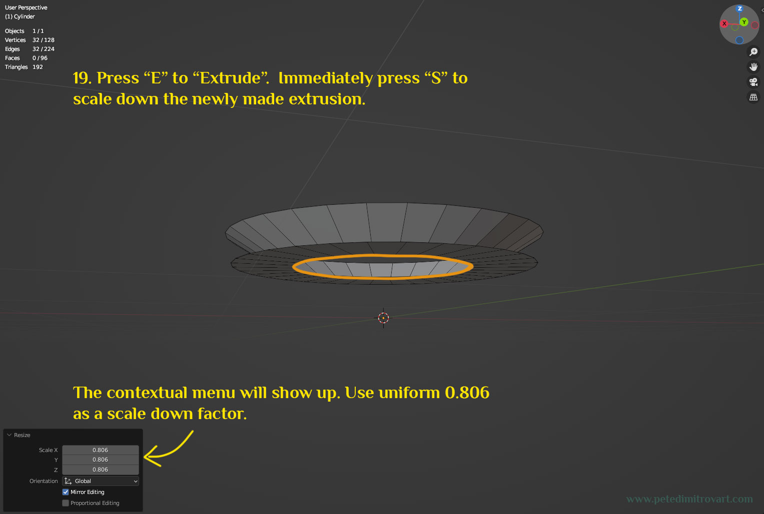
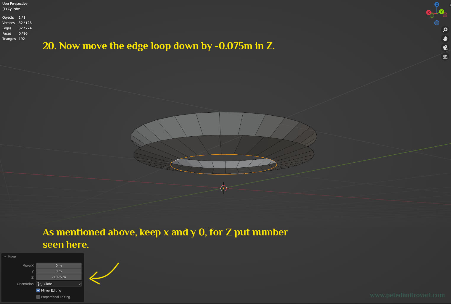
Image below: Now move the edge loop down by -0.075 m in Z axis. As mentioned, keep X and Y 0, for Z put -0.075 m.
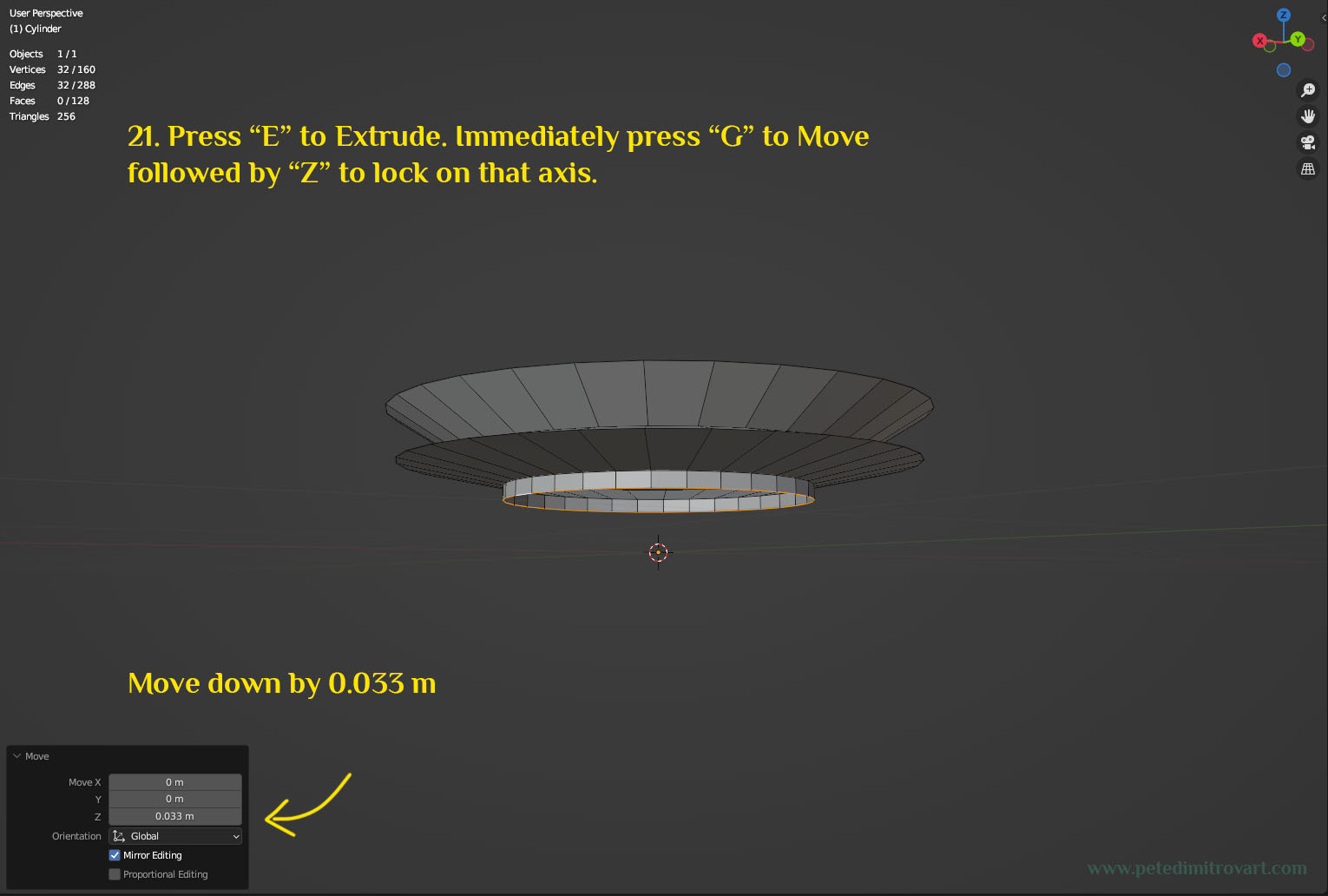
Press “E” to extrude. Immediately press “G” to move followed by pressing “Z” to lock on that axis. Move down the mouse, click anywhere. Put in 0.033 m in the context menu, as seen in image below.
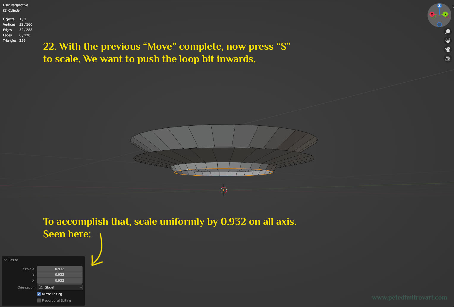
With the above image “Move” complete, now press “S” to scale. We want to push the loop a bit inwards. To accomplish that, scale uniformly by 0.932 on all axis. Seen in the image below.
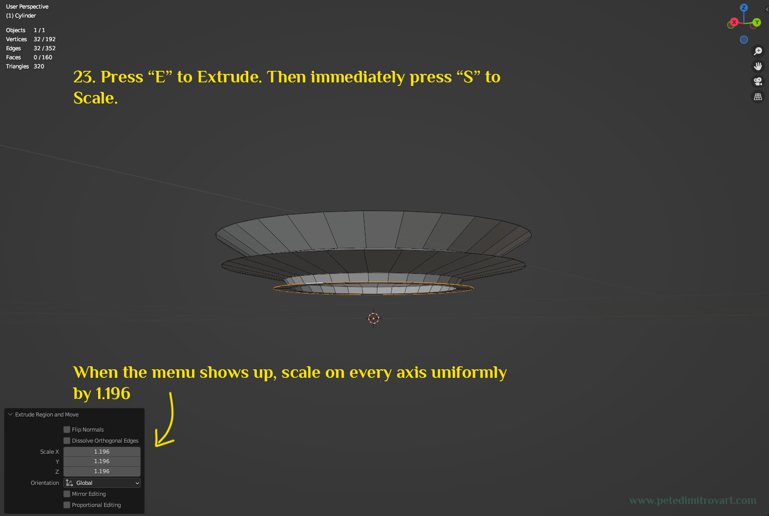
Let’s extrude a new loop of faces: Press “E” to extrude. Then immediately press “S” to scale. When the menu shows up, scale on every axis uniformly by 1.196 points (as seen in image below).
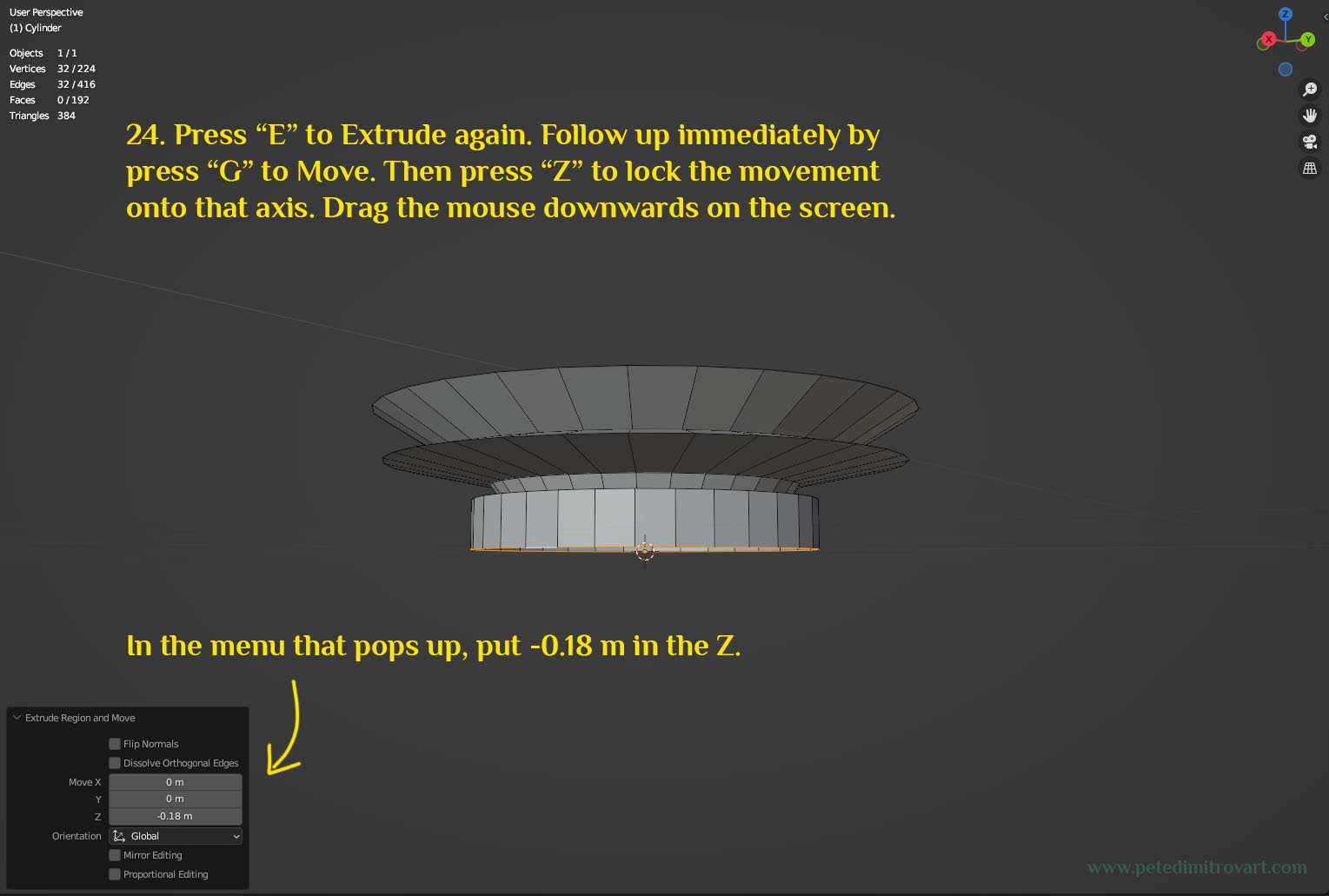
We want to extrude again: Press “E”. Follow up immediately by pressing “G” to “Move”. Then press “Z” to lock the movement onto that axis. Drag the mouse downwards on the screen. In the menu that pops up, put -0.18 m in the Z.
I keep repeating the hotkeys for common actions like Move, Extrude, Scale and how they work with keyboard and mouse clicks and movements. I do that so this tutorial is friendly to any Blender users, especially those who might be beginners. However if you are an advanced user, feel free to skim through most of the texts here and extract only the important info of by how much and in what axis to extrude, move, scale, rotate.
Step Eight
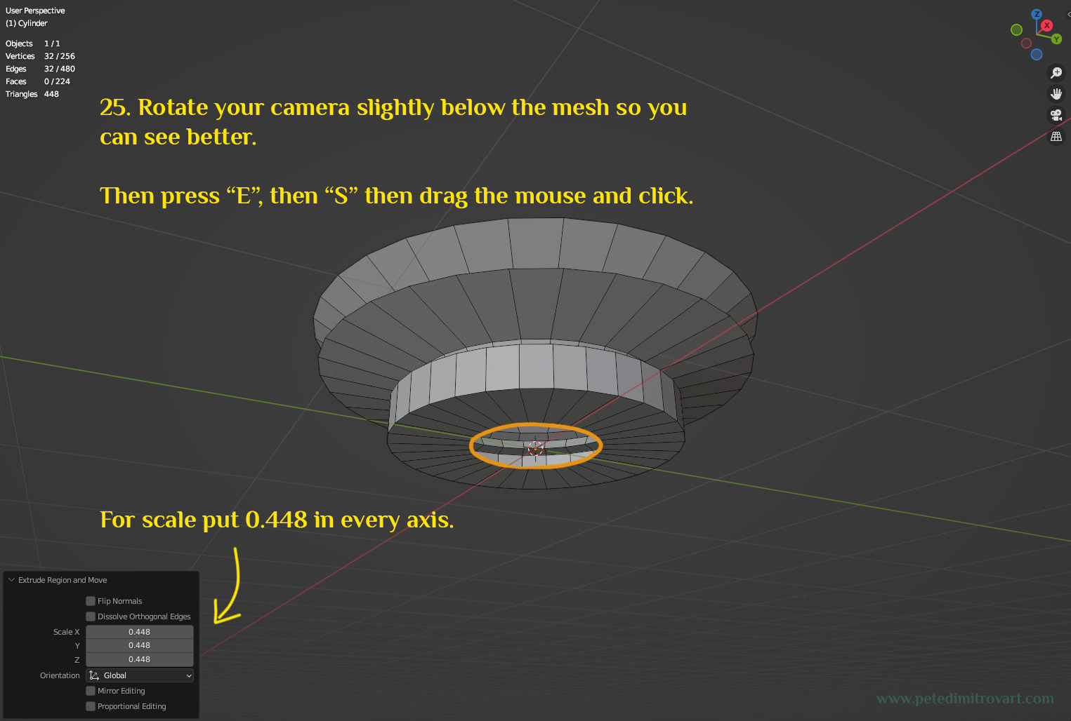
Rotate your camera slightly below the mesh so you can see better. Make sure you’ve selected the orange edge loop seen below. Press “E” then “S” then drag the mouse and click. When the context menu shows up, put 0.448 points in each axis uniformly.
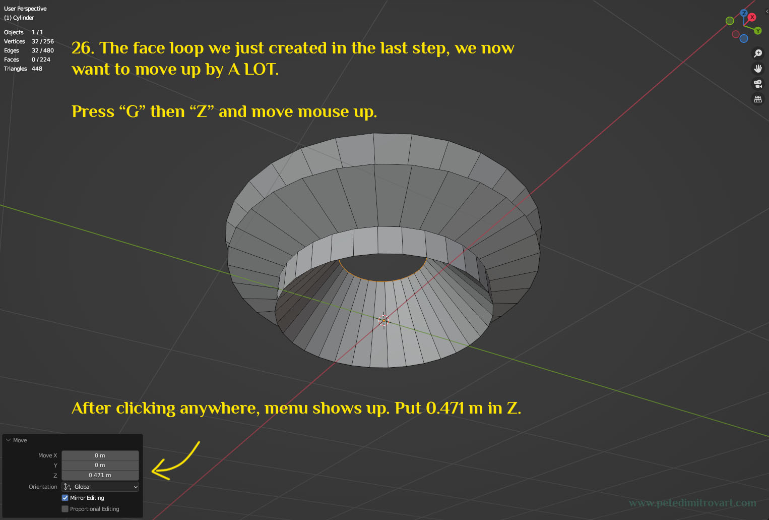
Now lets move that selecting upwards in space. The face loop we just created in the last step, we now want to move up by A LOT. Press “G” then “Z” and move mouse up. After clicking anywhere, menu shows up. Put 0.471 m in the field for Z.
Lets rotate our camera on the upside again. In the picture below we don’t do any new actions. Instead we look at how your mesh should look so far, when looked from the above angle.
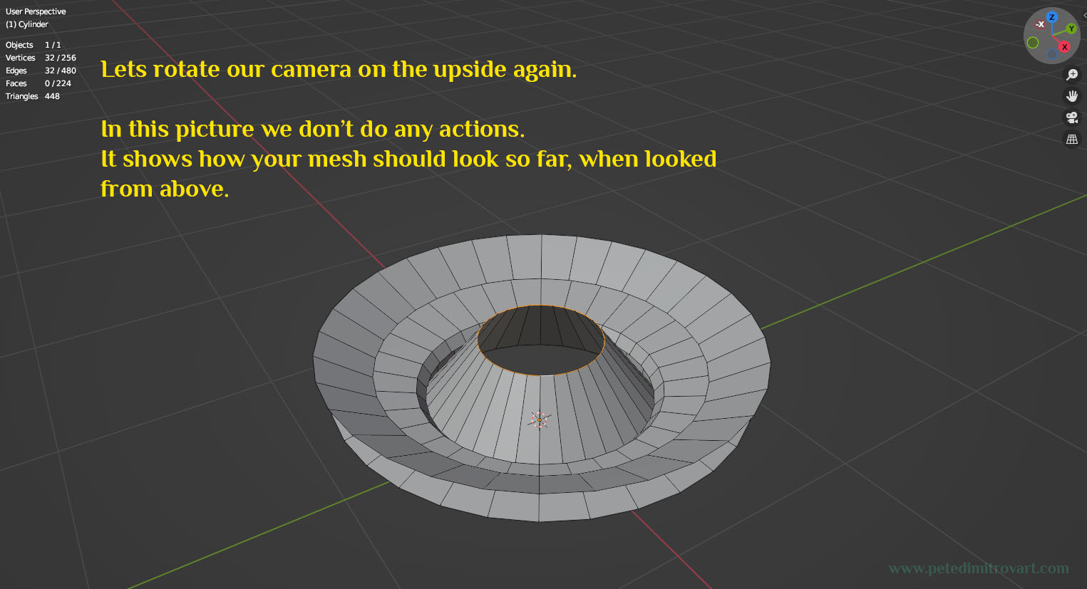
I mention this in a step later on, but: if your mesh so far looks roughly similar, but is not identical, and has some differences, don't worry about it. This VFX relies on creating a --vortex basin-- but the rules for making that are not set in stone. You can have slight differences, or some of your loops might be slightly misplaced up or down, compared to mine in the pics above. That doesn't mean that your VFX won't turn out just fine. It will look good.
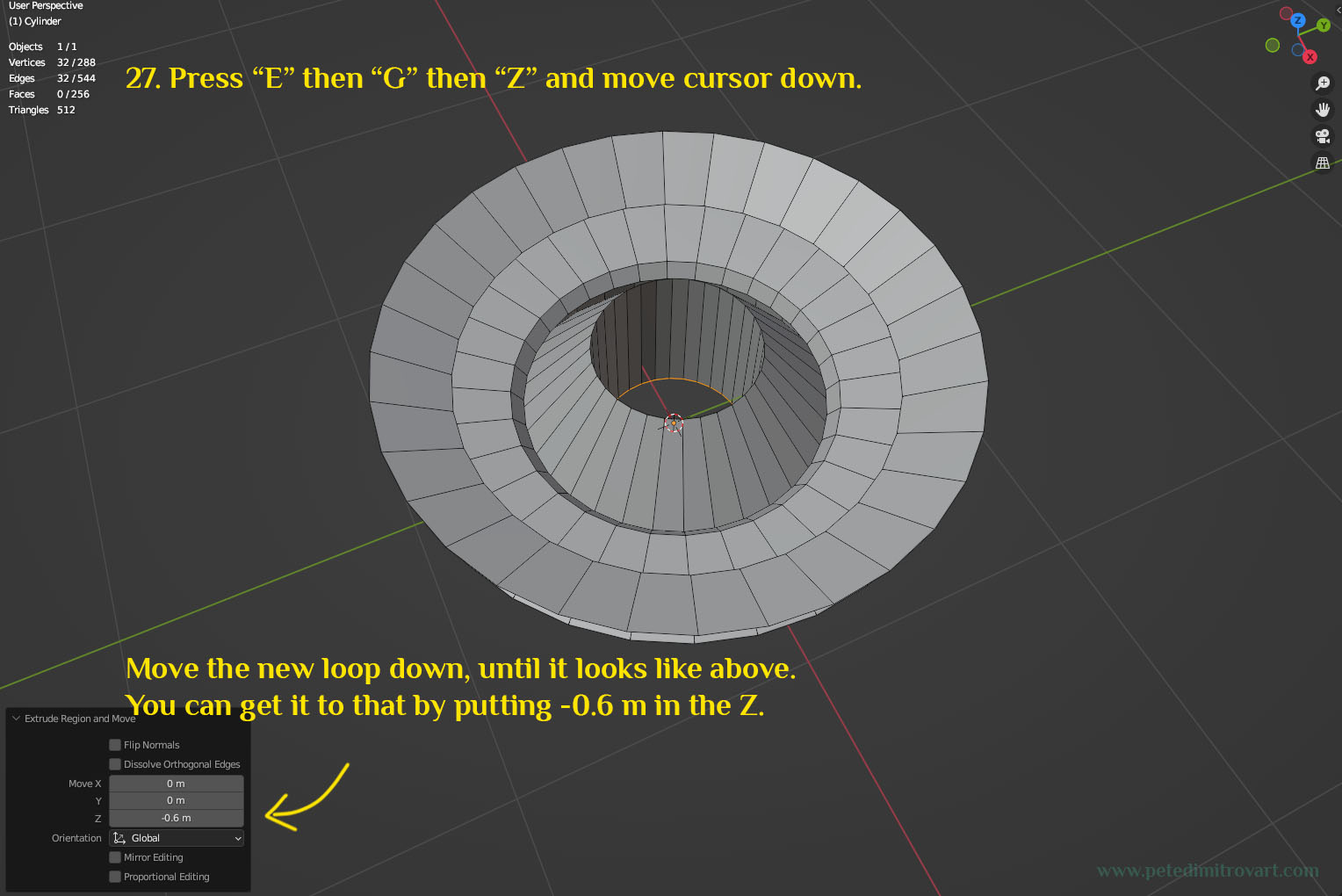
Press “E” then “G” then “Z” and move cursor down. We are now moving the newly extruded loop down. In the Z put -0.6 m. Seen below:
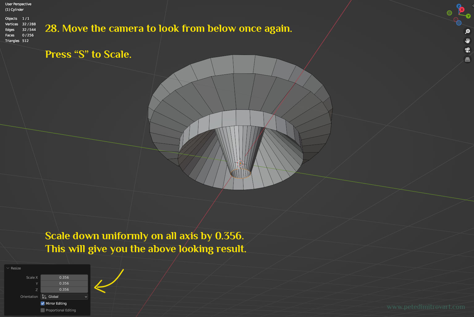
Lets rotate the camera to look from below once again. Then press “S” to scale. Scale down uniformly on all axis by 0.356 points. This will give you the result like in the image below.
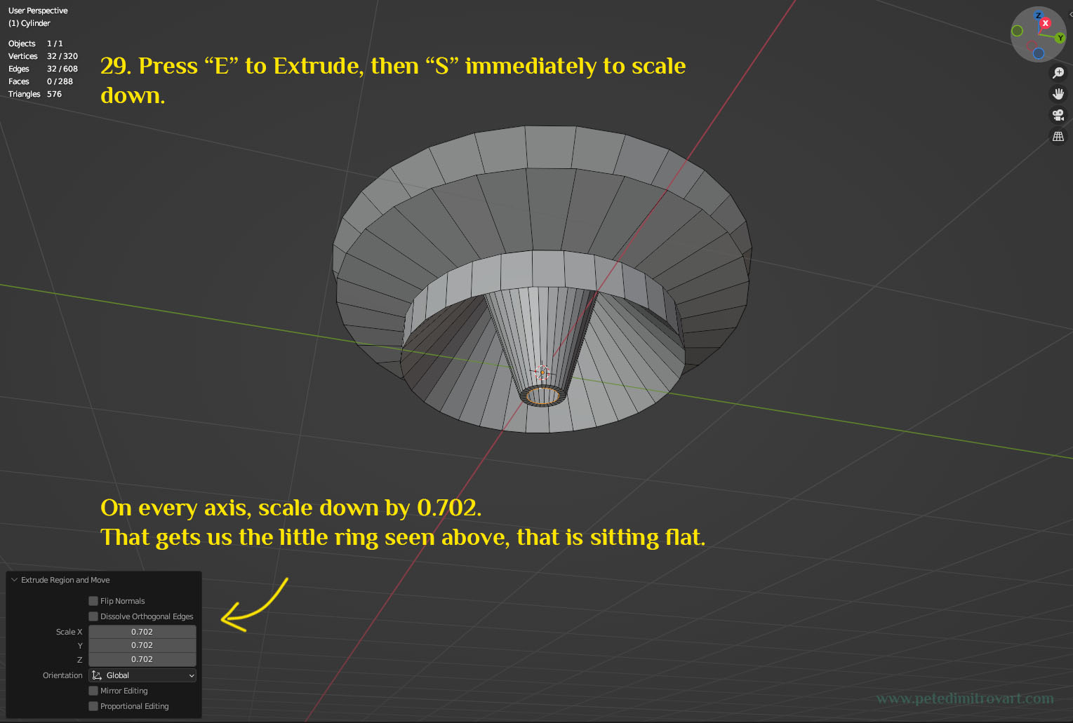
Press “E” to extrude, then “S” immediately to scale down. On every axis, scale down by 0.702 points. That gets us the little ring seen in the image below, that is sitting slightly flat.
Step Nine
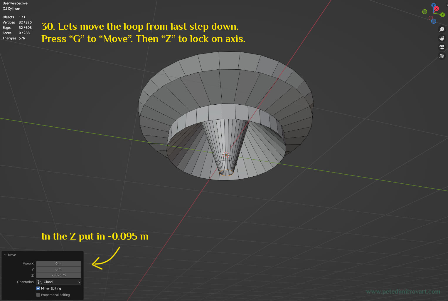
Lets move the loop from last step down in space. Press “G” to “Move”. Then “Z” to lock on that axis. In the Move settings in context menu, put in minus 0.095 m for Z.
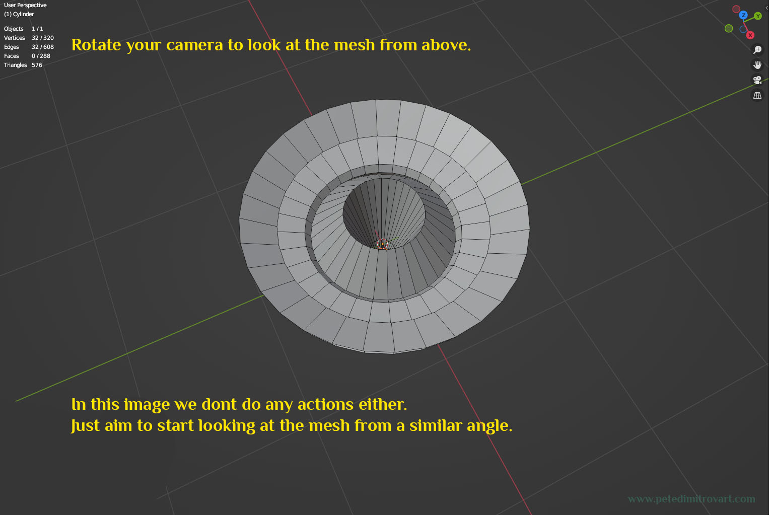
Next, rotate your camera to look at the mesh from above (so you can see it in a similar way to the image below). In this image we don’t do any actions. We just want to start looking at the mesh from this angle.
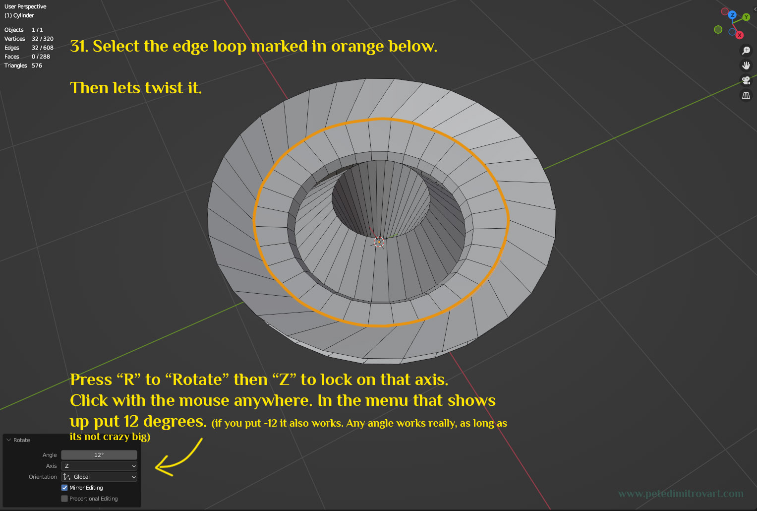
Select the edge loop marked in orange in the image below. Then lets twist it. Press “R” to “Rotate” the selection, then “Z” to lock on that axis. Click with the mouse anywhere. In the menu that shows up, put 12 degrees. (if you put say minus 12, it will also work. Any angle works really, as long as its not a crazy big angle.)
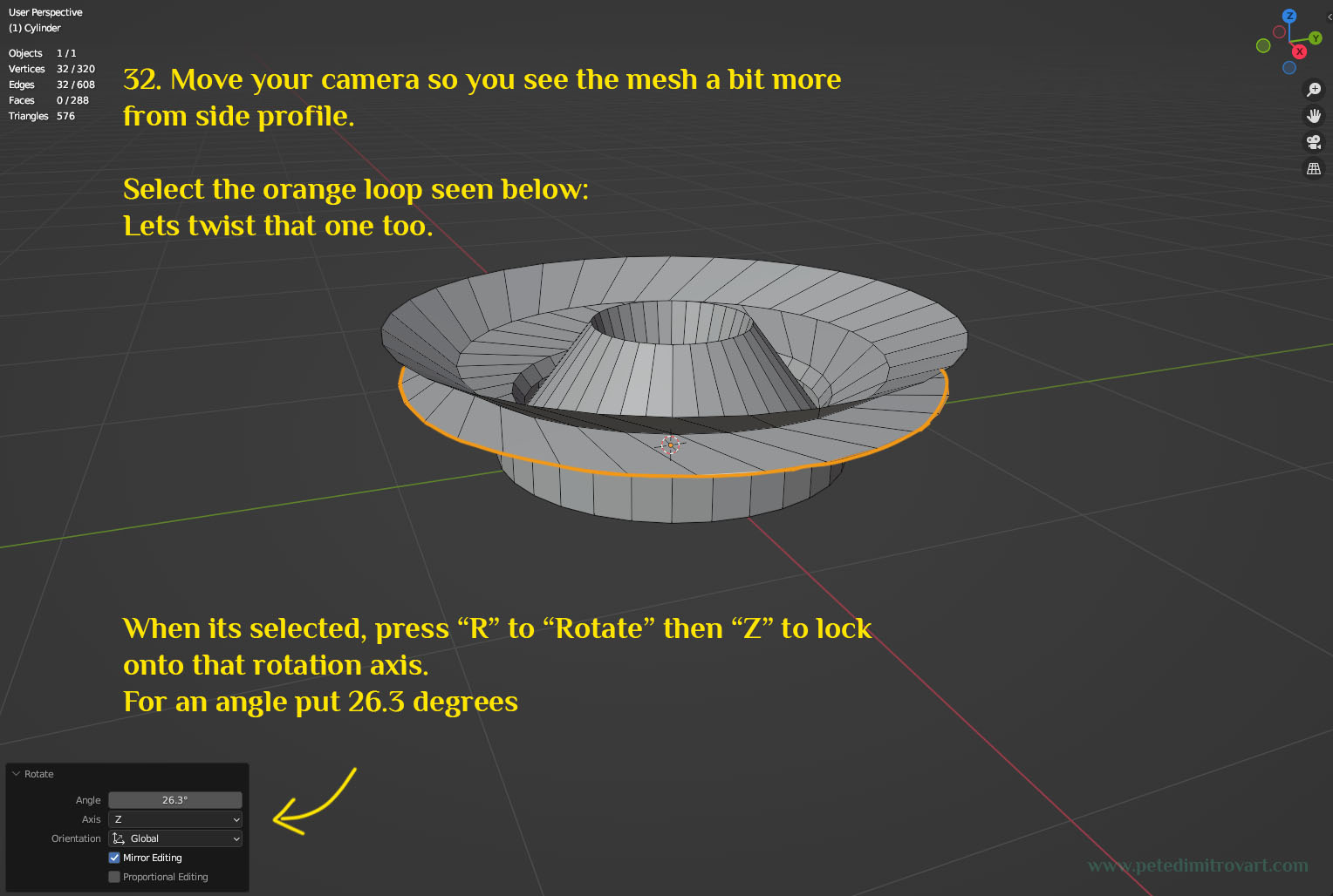
Move your camera so you see the mesh a bit more from the side. Select the orange loop seen below. Lets twist that one too. When it’s selected, press “R” to “Rotate” then “Z” to lock onto that rot axis. For an angle put 26.3 degrees.
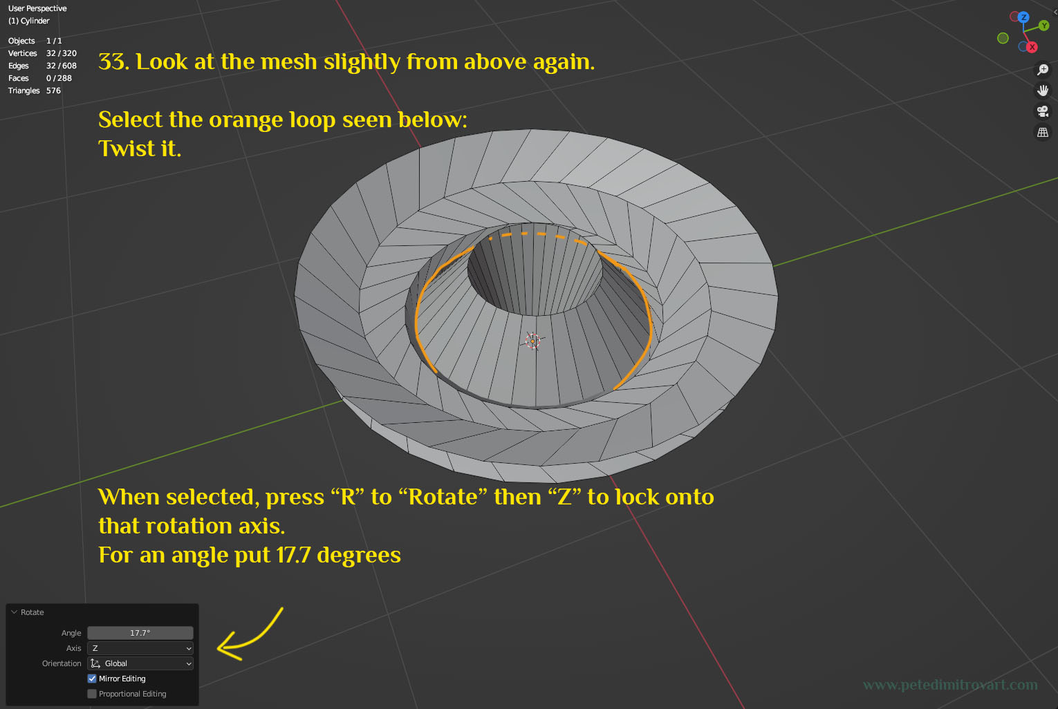
Look at the mesh slightly from above again. Select the orange loop seen below. Twist it. Put a rotation angle of 17.7 degrees.
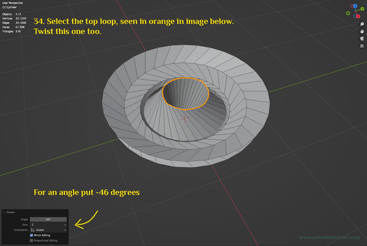
Select the top loop, seen in orange in the image below. Twist this one too. For an angle put minus 46 degrees.
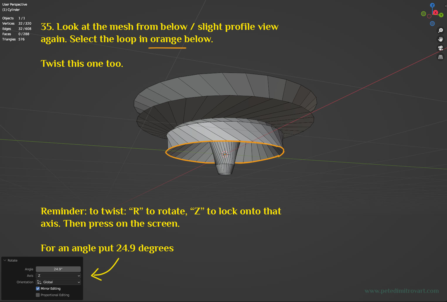
Look at the mesh from below / slight profile view again. Select the loop in orange below. This this one too. Reminder: to twist use “R” to rotate, “Z” to lock onto that axis. Then press on the screen. In the context menu put an angle of 24.9 degrees.
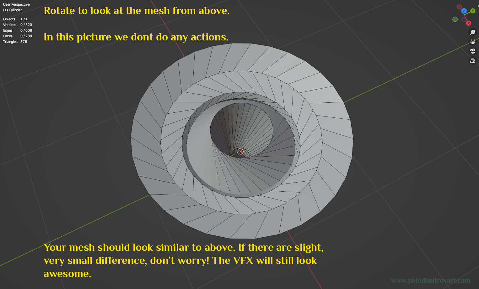
Rotate to look at the mesh from above. In this picture we don’t do any actions. Your mesh should look similar to above. If there are slight, very small differences, don’t worry. The VFX will still look awesome.
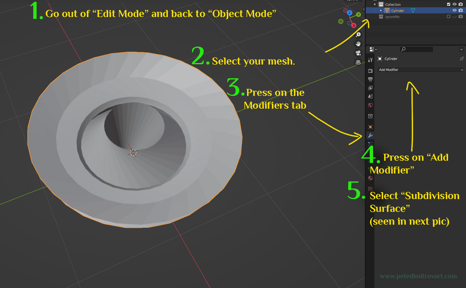
Go out of “Edit Mode” and back to “Object Mode” (reminder - for me, I do that by pressing TAB on the keyboard. You might have a different keybinding though.) Select your mesh - either by clicking on it or using the Collection Manager. Look at the right hand menus. Click on the “Modifiers” tab (its icon is in blue color and looks like a wrench). To the right of it then click “Add Modifier”. From the menu that shows up in picture after the next one, select “Subdivision Surface” as a modifier.
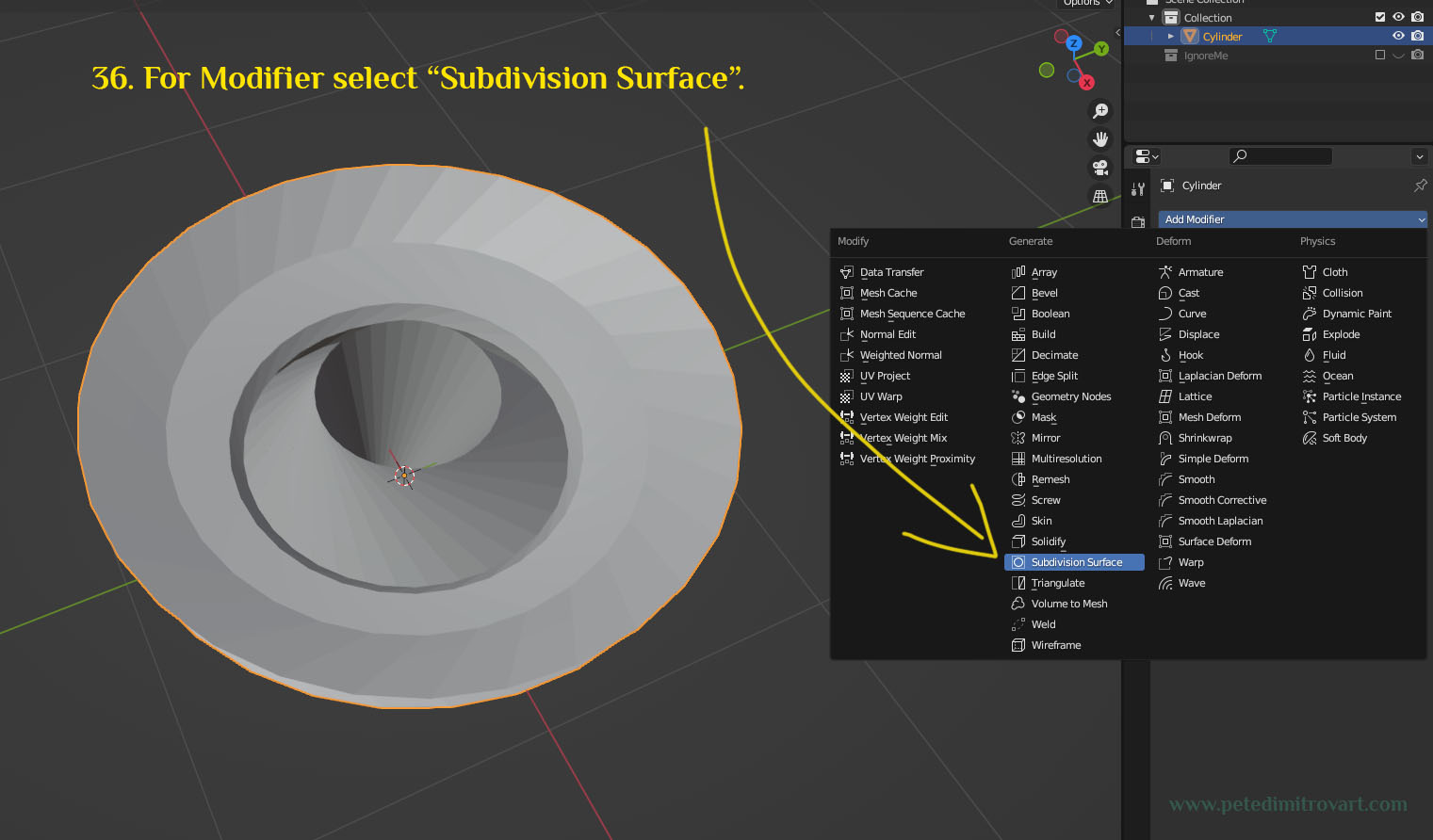
For Modifier, as mentioned before, select “Subdivision Surface”.
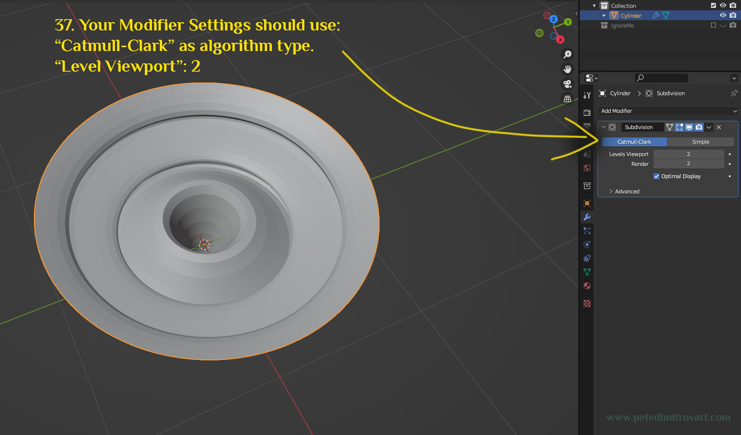
Your modifier settings should use the following: Catmull-Clark as algorithm type. Level Viewport: 2.
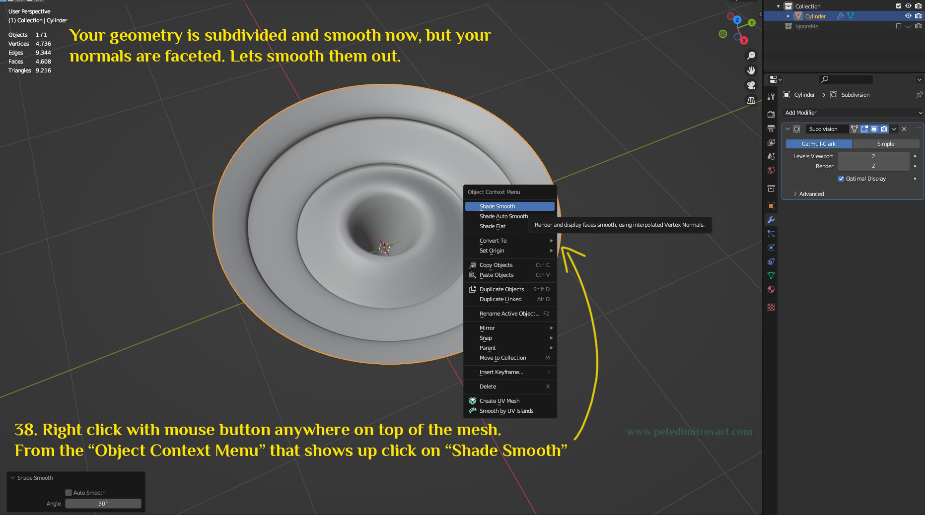
Your geometry is subdivided and smooth now, but your normals are faceted. Lets smooth them out. Right click with mouse button anywhere on top of the mesh. From the “Object Context Menu” that shows up click to select “Shade Smooth”.
Step Ten
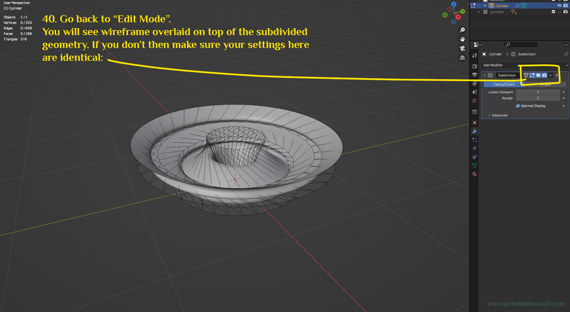
Go back to “Edit Mode”. You will see wireframe overlaid on top of the subdivided geometry. If you don’t, then make sure your settings here are identical as seen in the image below (step 39 is skipped due to numerical error, there are no images missing through).
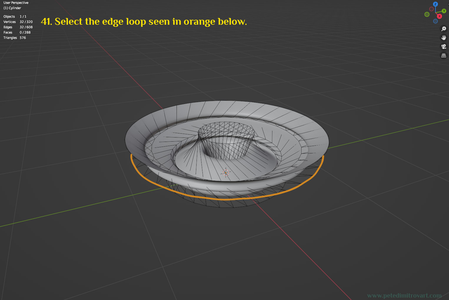
Select the edge loop seen in orange below.
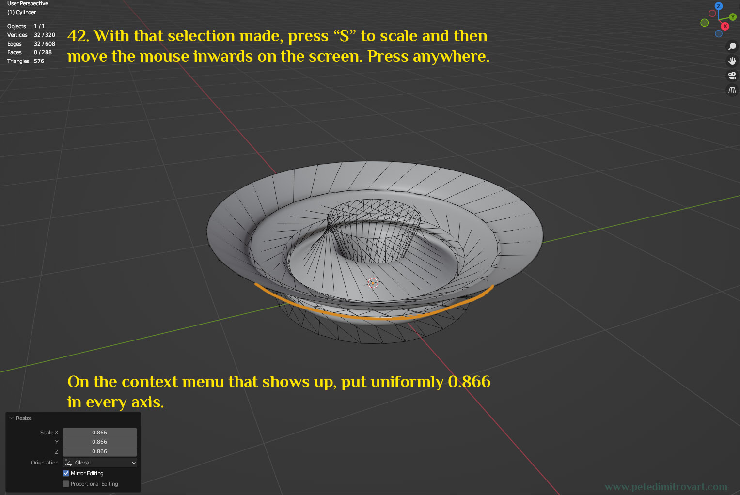
With that selection made, press “S” to scale and then move the mouse inwards on the screen. Press anywhere. On the context menu that shows up, put uniform scale of 0.866 points in every axis.
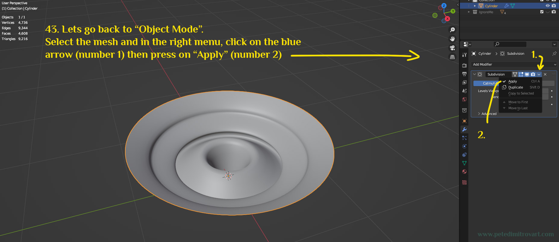
Lets go back to “Object Mode”. Select the mesh and in the right menu click on the blue arrow (seen in the screenshot below marked as number 1) then press on “Apply” (marked as number 2).
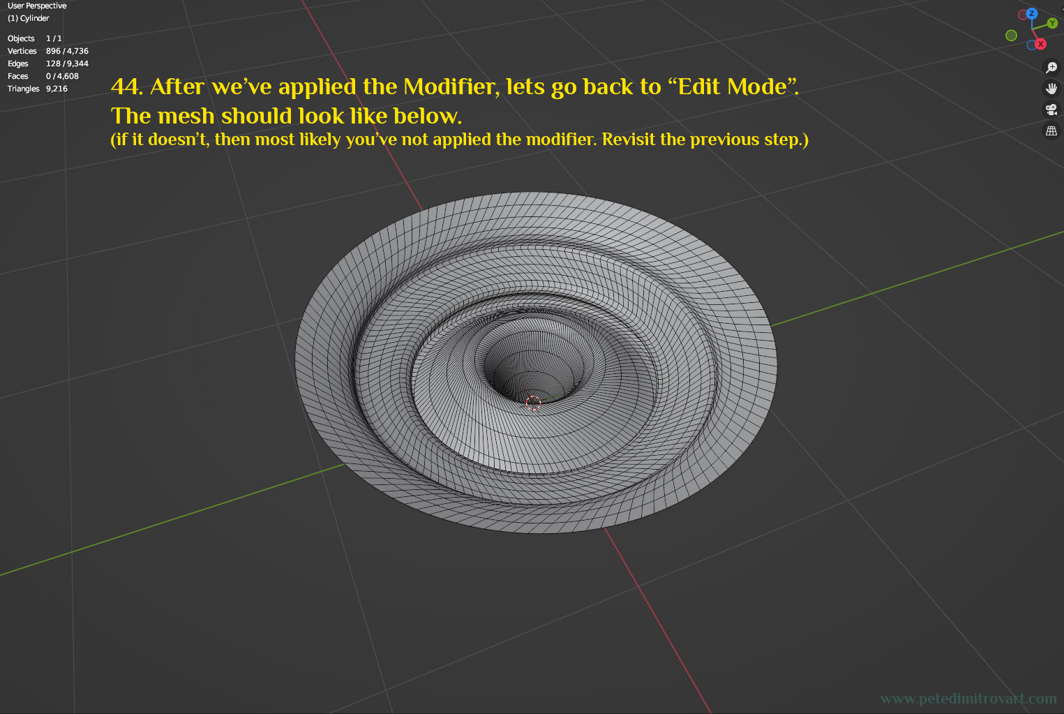
After we’ve applied the modifier, lets go back to “Edit Mode”. The mesh should look like below (if it doesn’t then most likely you’ve not applied the modifier yet. As such revisit the previous step.).
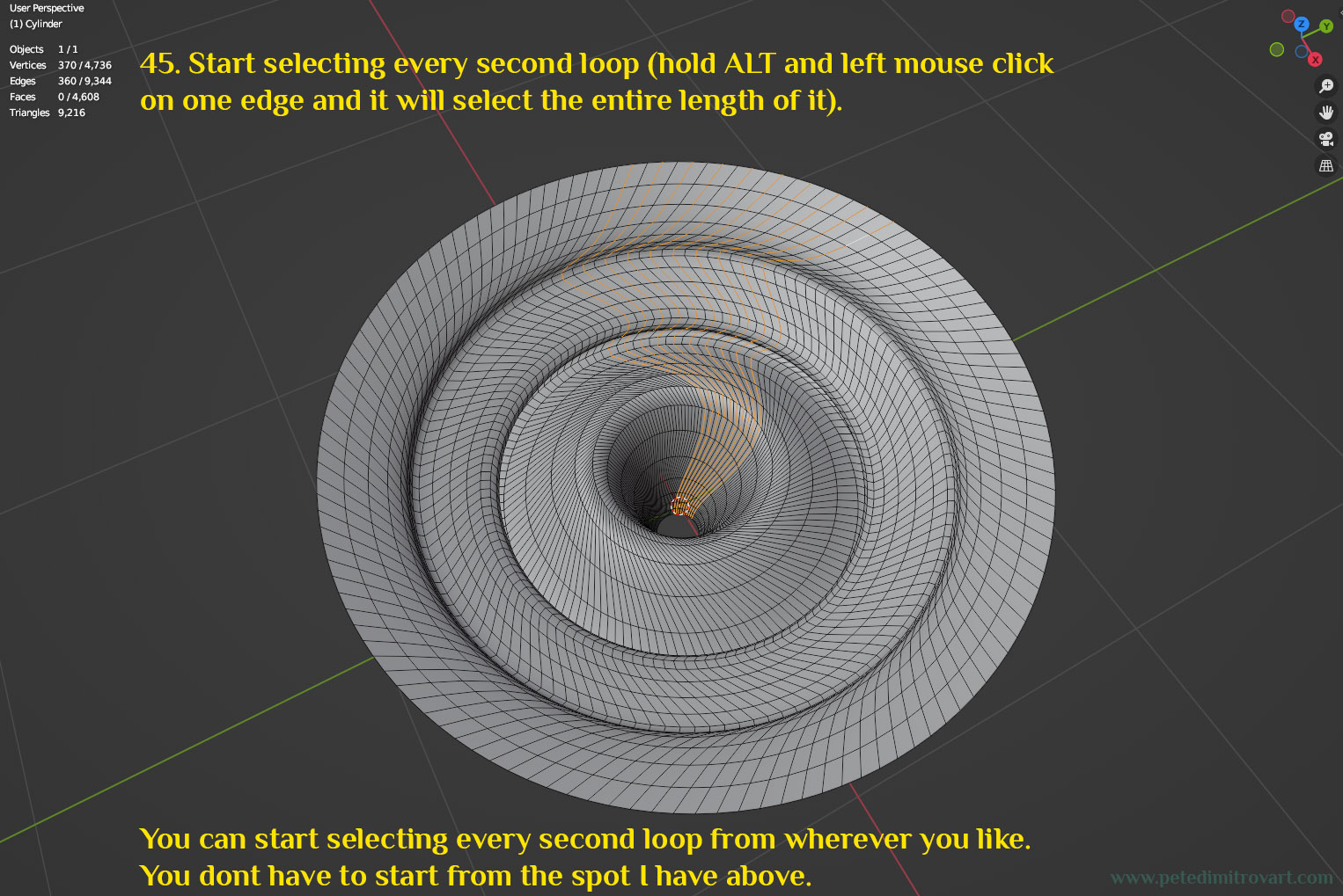
Start selecting every second loop (hold ALT on the keyboard and then left mouse click on one edge and it will select the entire length of it). You can start selecting every second loop from wherever you like on the mesh. You don’t have to start from the spot I have started from in the image.
Step Eleven
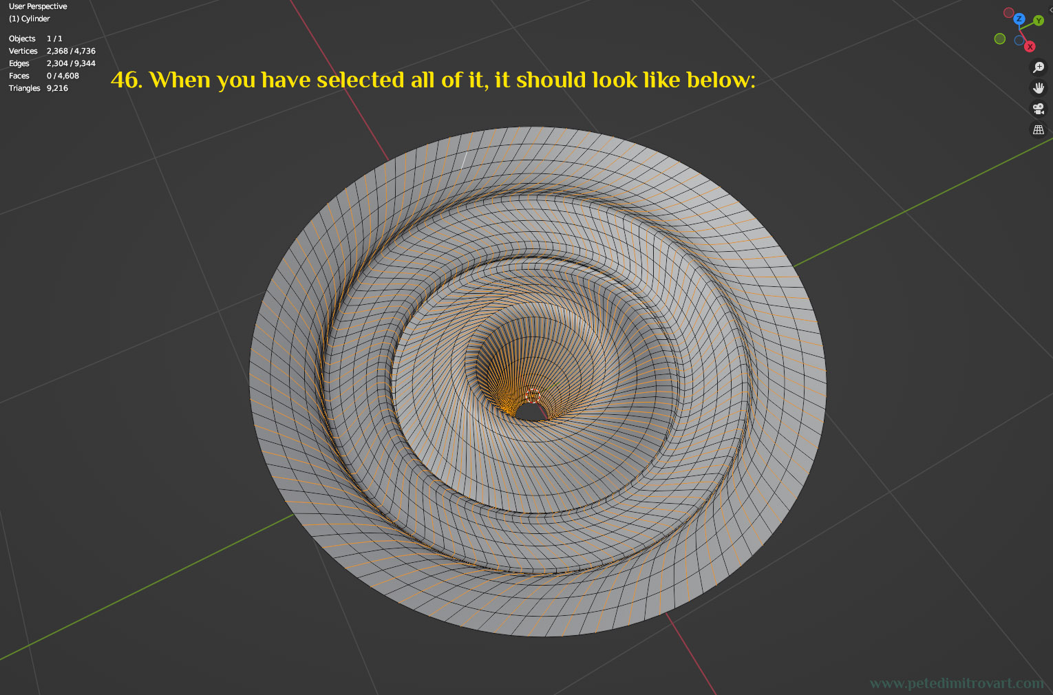
When you have selected every second loop, your selection should look like in the image below:
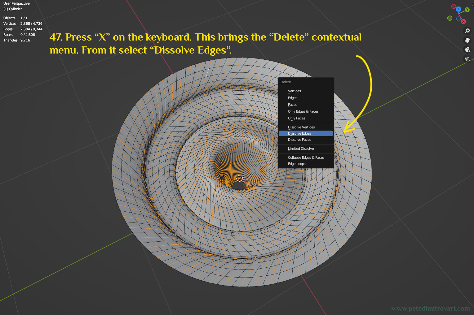
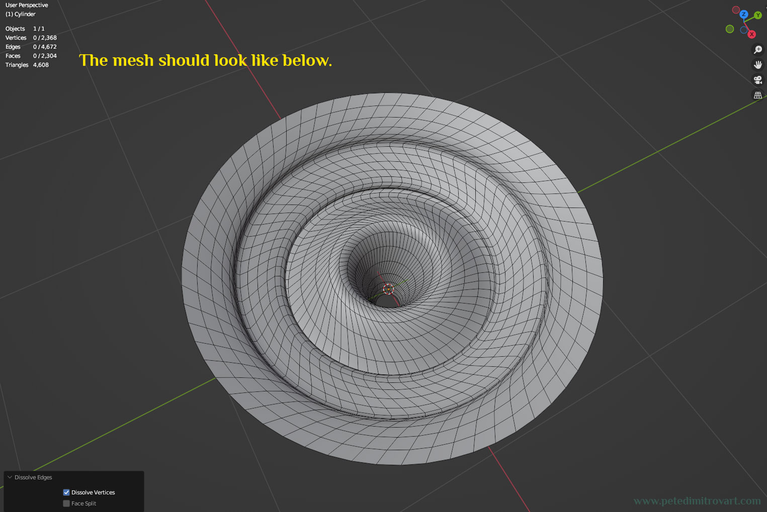
Press “X” on the keyboard. This brings the “Delete” contextual menu. From that menu select “Dissolve Edges”.
The result of deleting the edges should give you a mesh that looks like this:
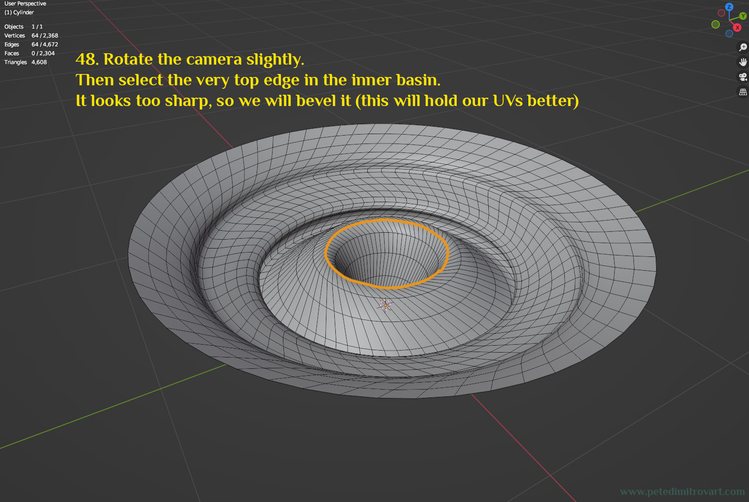
Rotate the camera slightly. Then select the very top edge in the inner basin (it’s marked in orange in the image below). That edge looks too sharp, so we will bevel it (this will hold our UVs better).
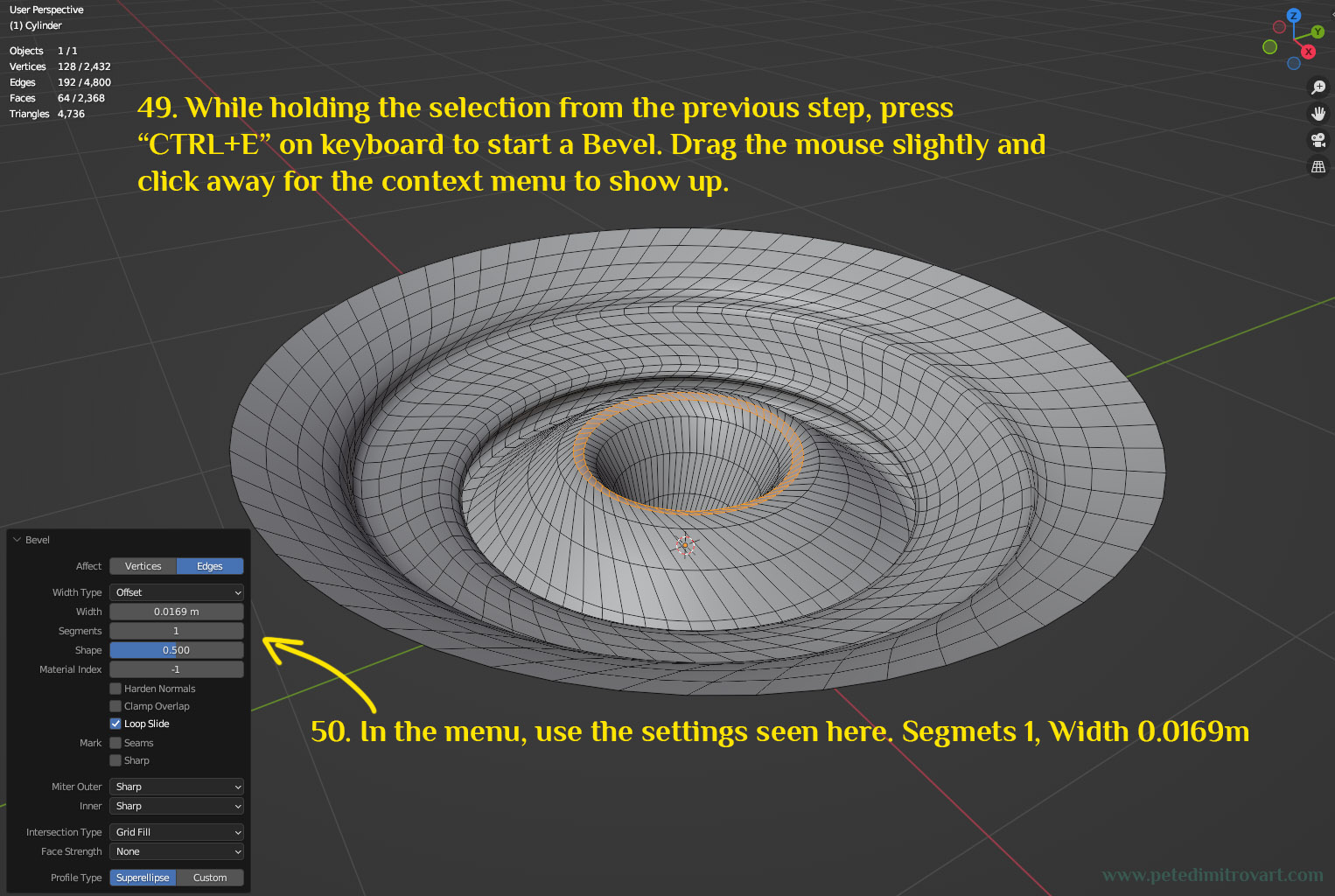
While holding the selection from the previous step, press “CTRL+E” on the keyboard to start a Bevel. Drag the mouse slightly and click away for the context menu to show up. In the menu, use the settings seen below: “Segments: 1” and “Width: 0.0169m”.
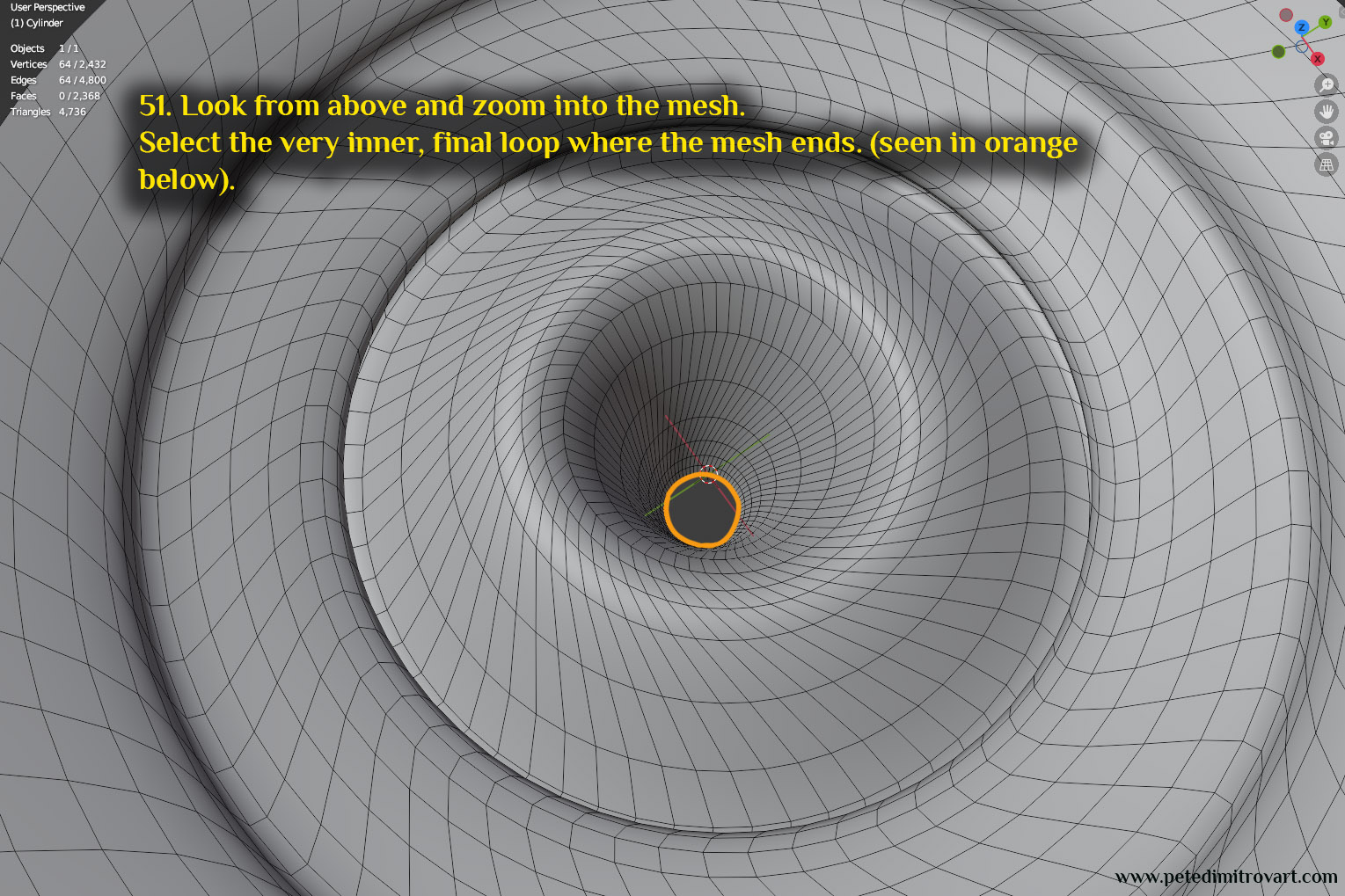
Look from above and zoom into the mesh. Select the very inner, final loop, where the mesh ends. Seen in orange below.
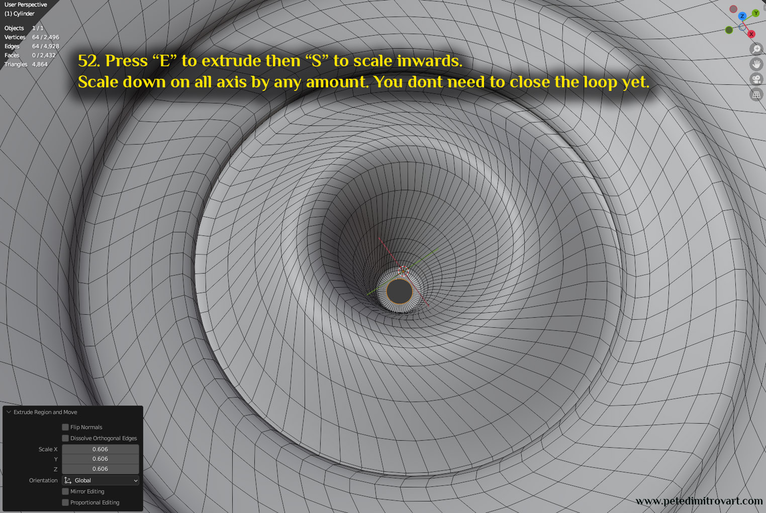
Press “E” to extrude then “S” to scale inwards. Scale down on all axis by any amount. You don’t need to close the loop yet.
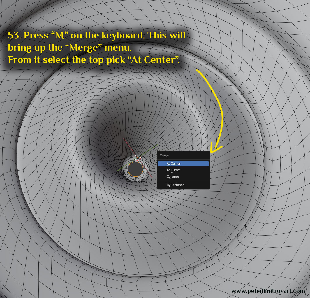
Press “M” on the keyboard. This will bring up the “merge” menu. From it select the top pick called “At Center”.
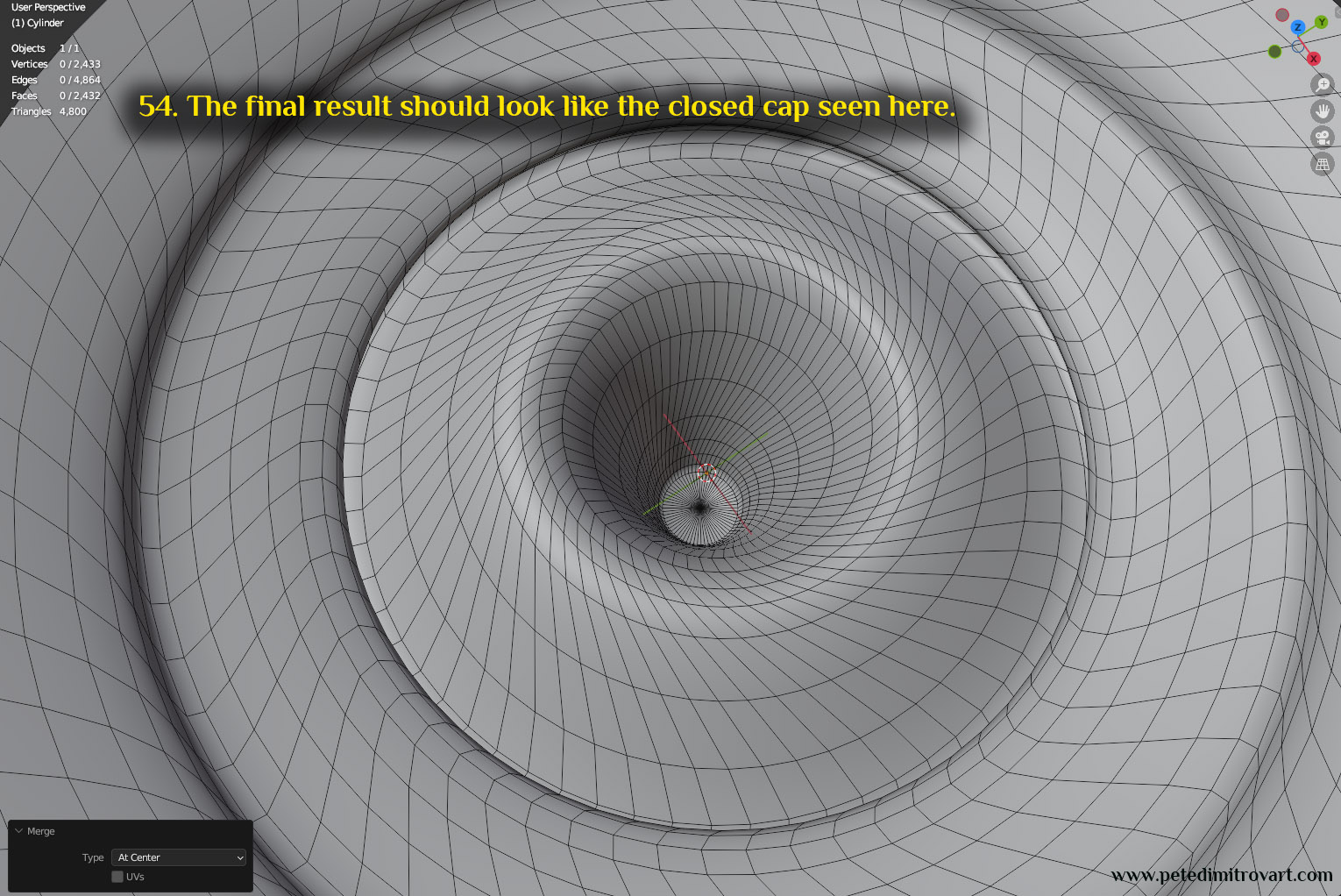
The final result should look like the closed cap seen here:
With all of the above, our geometry is done. Now lets double check our normal directions of our faces. Then lets UV map. Those are the two final steps before we call all of this done.
Step Twelve - Faces Direction
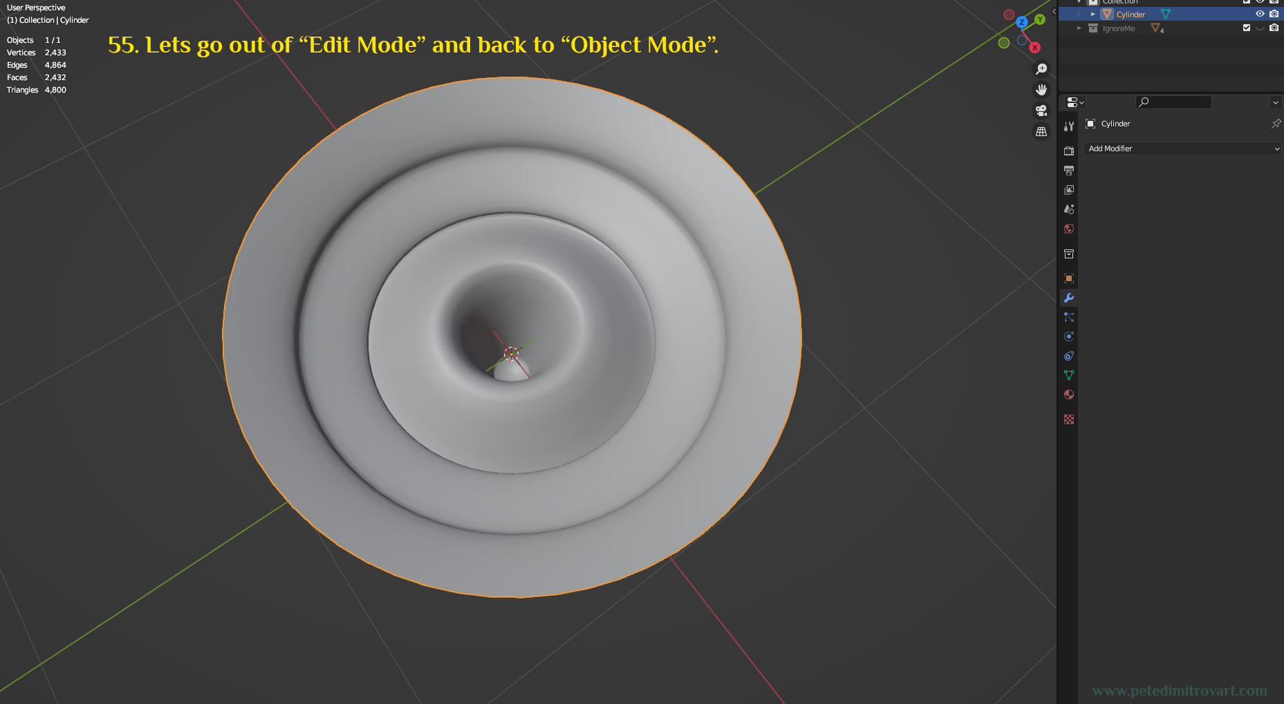
Let’s go out of “Edit Mode” and back into “Object Mode”.
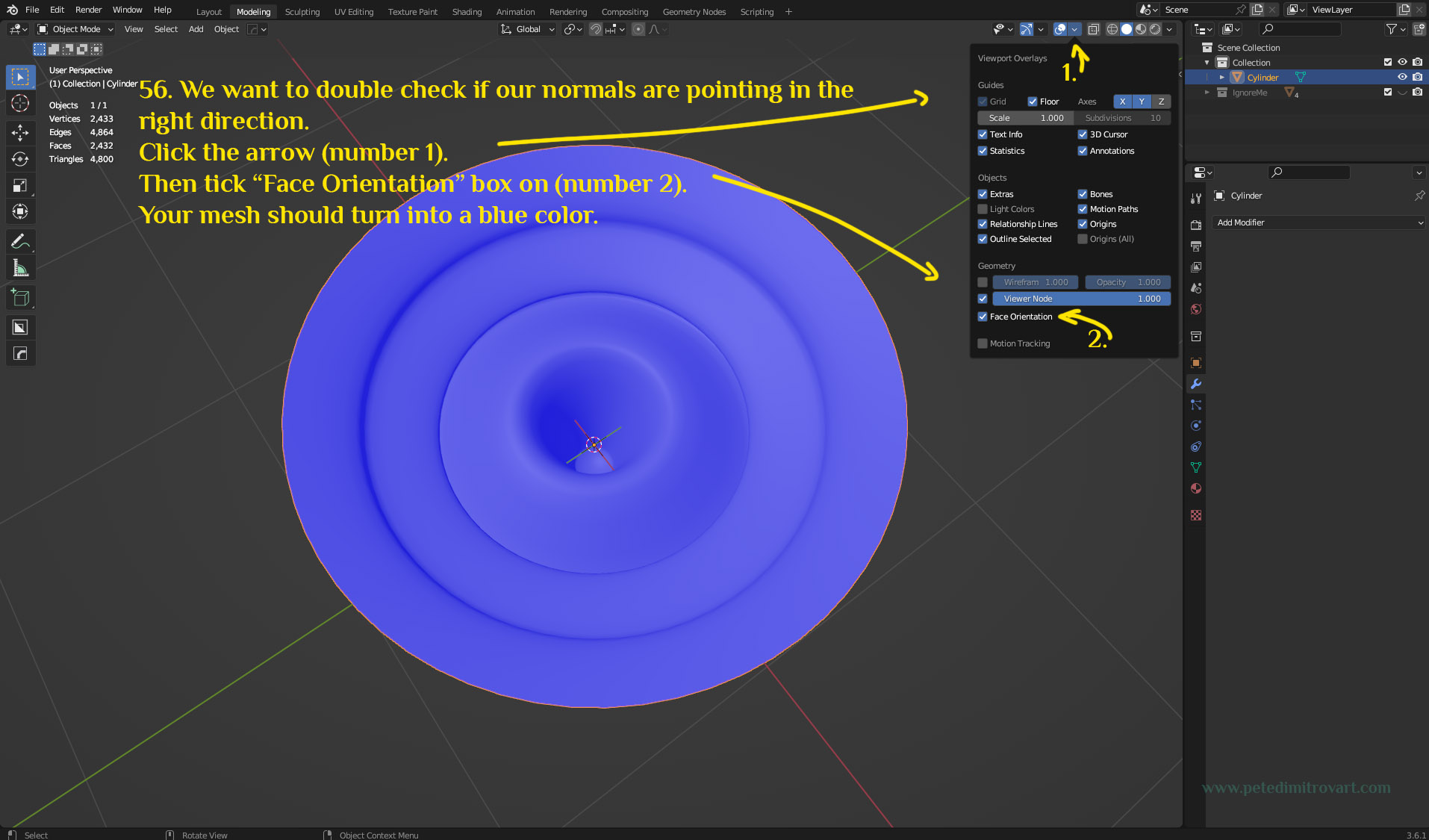
As mentioned, we want to double check if our normals are pointing in the right direction. In Blender, unlike Maya and 3Ds Max, when the faces point in the wrong direction, we still see shaded result. In the other two modelling softwares instead we would be seeing invisible mesh, and when rotating the camera we would understand thats the issue. Here instead we want to enable “Face Orientation” viewport setting so we can observe any issues.
Click the arrow (number 1 marked in the image below.) Then tick ON the “Face Orientation” box in the menu that pops up. This is marked as (number 2) in the image below. Your mesh should then turn into a blue color.
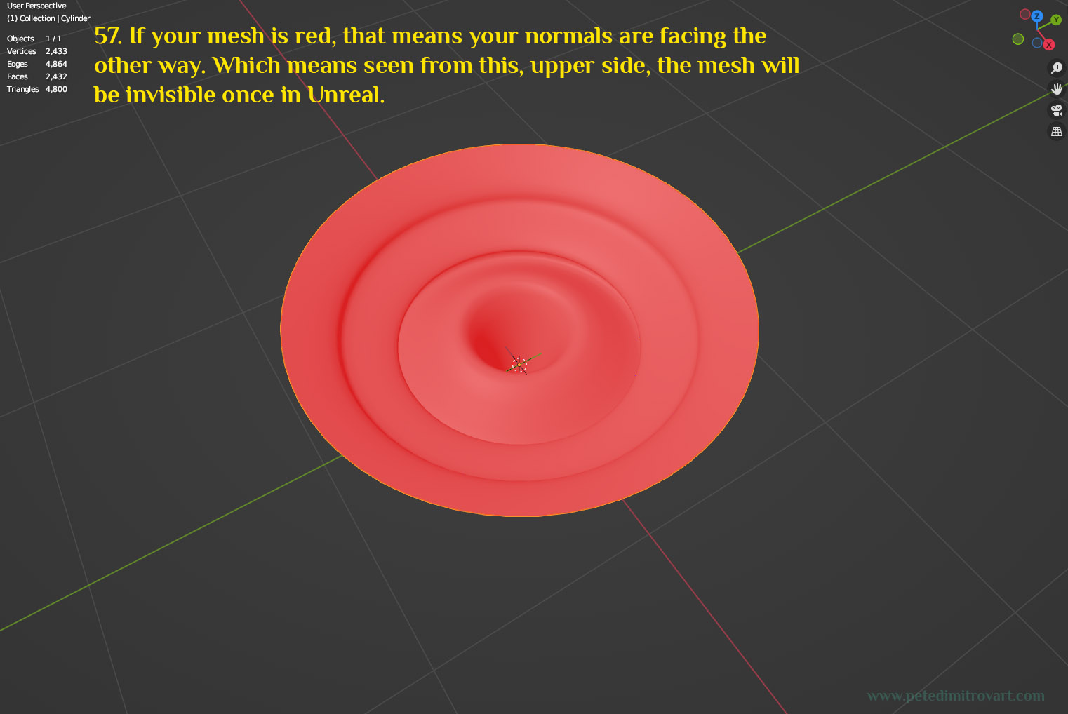
If your mesh is red, that means your normals are facing the other way (inverted normals). This means that when seen from this upper side, the mesh will be invisible once in Unreal.
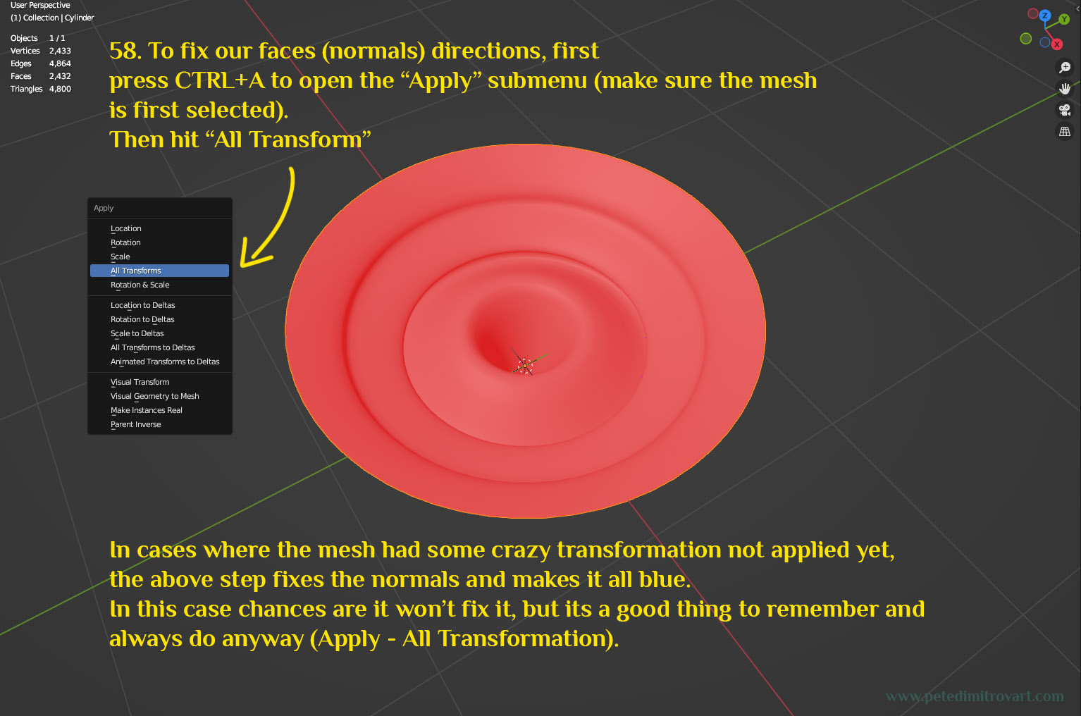
To fix our faces direction (normal directions), first press CTRL+A to open the “Apply” submenu (make sure the mesh is first selected). From that menu select “All Transform”. In cases where the mesh had some crazy transformations not applied yet, the above step fixes the normals and makes it all blue. In this case chances are it wont fix it for you, but its a good thing to remember and always do anyway (to Apply - All Transformations).
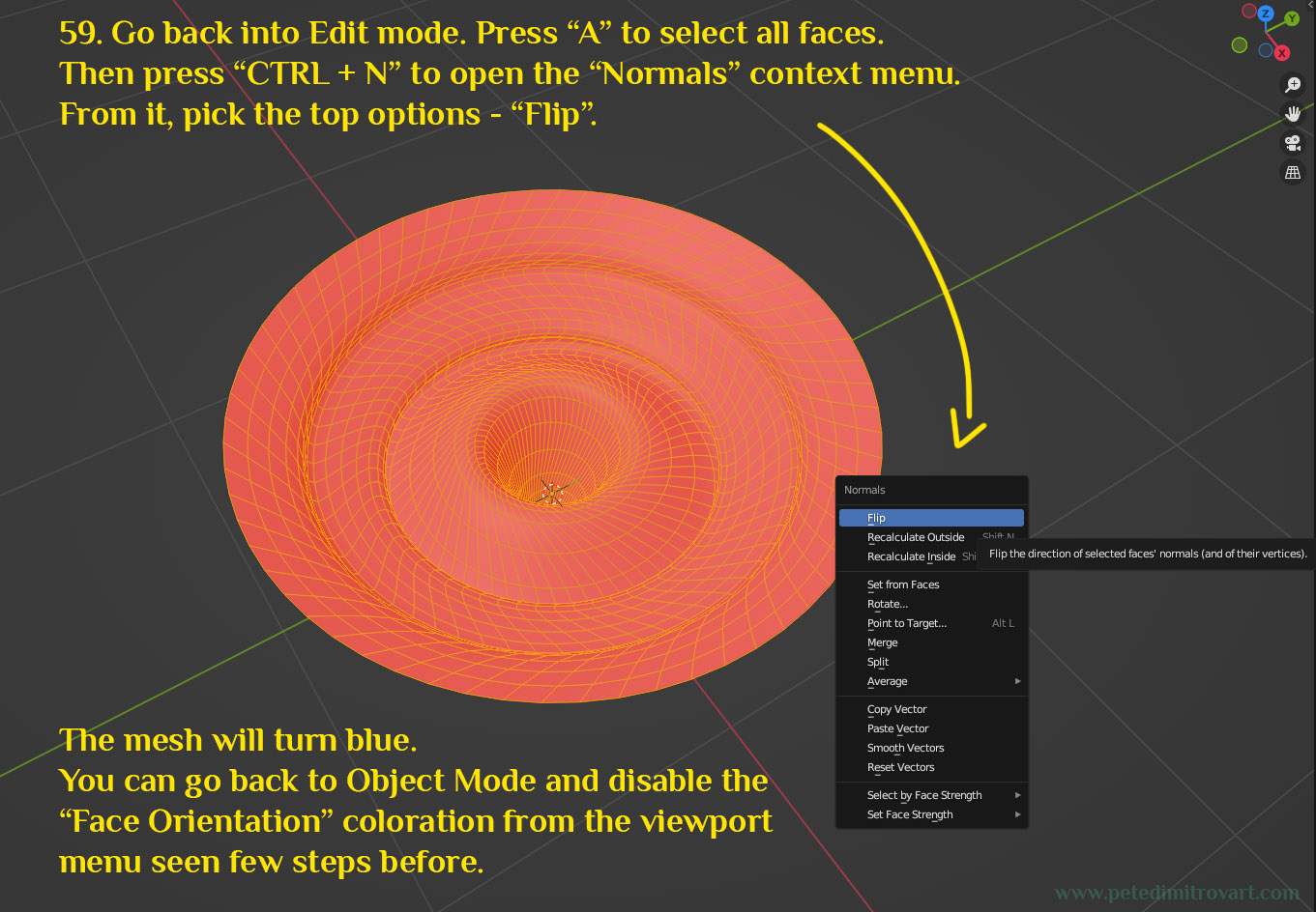
With All Transformation applied, if your mesh is still red, go back into “Edit Mode”. Press “A” to select all faces. Then press “CTRL + N” to open the “Normals” context menu. From it pick the top option - “Flip”. The mesh will then turn blue. You can go back to Object Mode and disable the “Face Orientation” coloration from the viewport menu seen few steps before.
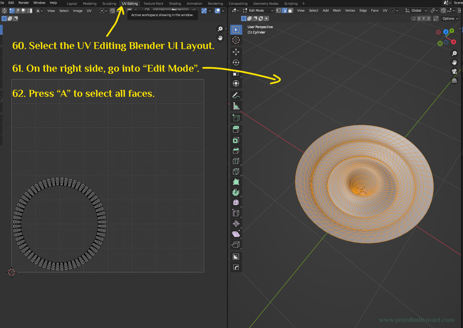
Step Thirteen - UV Mapping
Select the UV Editing Blender UI layout. On the right side, go into “Edit Mode”. Press “A” to select all faces.
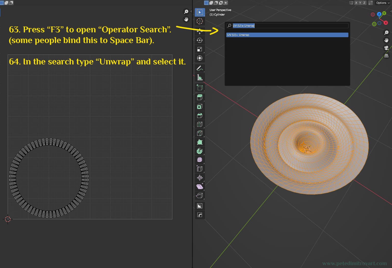
Press “F3” to open “Operator Search” (some people bind this to Space Bar on keyboard). In the search type “Unwrap” and select it.
Tip:
If you need more context as to what the - Menu Search - or - Operator Search - is and how to open it, check out the link to the official Blender Docs that I've put below.
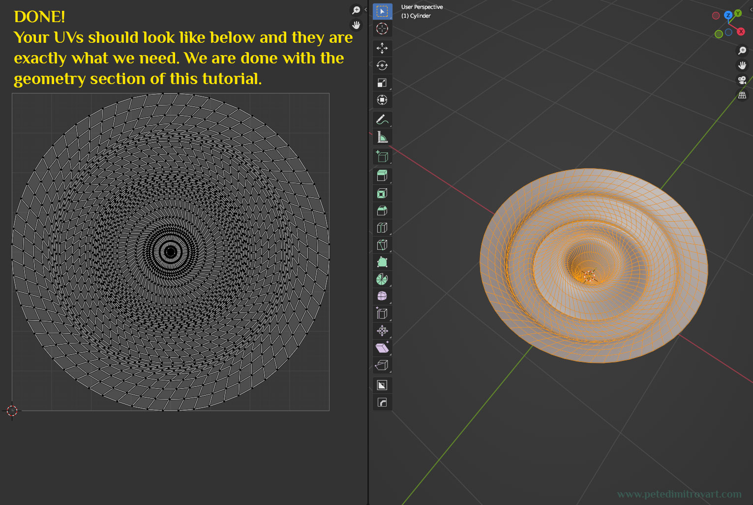
We are done! Your UVs should look like below and they are exactly what we need. We are all wrapped up with the geometry section of this tutorial.
Conclusion
This completes the geometry we need. You can export you Static Mesh as you usually do, and import it in Unreal. If you are using Unreal 5, then tick “Import as Nanite” off, as we need this as ordinary static geometry. We will explain why that is in the next parts of the tutorial. That is where we will cover how to created the textures necessary and then how to assemble the Unreal material shader.
Next part of the tutorial: “The Amarantos Ritual - 06 - Vortex VFX Tutorial - Part Two”. It covers creating the textures necessary for the VFX. We will be working in Substance Designer.
Cheers,
Pete.
If you enjoyed this blog post, consider subscribing in the form below. That way you will get a notification the next time I publish a new blog.